Do not loosen the impeller, fan or balancing weight.
Installation and electrical connection should only be carried
out by trained and qualified personnel.
Wear safety shoes and gloves for handling!
•
The system manufacturer or the machine builder is
responsible that the inherent installation and security infor-
mation are harmonized with the valid standard and guide-
lines (DIN EN ISO 12100 / 13857).
– Design RE, RH, RM, for attachment to fixed motor
flange: use property class 8.8 screws and provide with
suitable screw locking. Permissible tightening torque:
M4 = 2.1 Nm; M6 = 9.5 Nm; M10 = 40 Nm; M12 = 70
Nm; related to friction coefficient according to DIN EN
ISO 4014 µ
tot
= 0.12
– Motor frame size 068: comply with stated length of
thread engagement
– Design RZ, RK without add on parts, attachment to
axle ends according to manufacturers specifacions.
– Design RG, RF, RD, RA: fasten to the flange or
mounting bracket dependent on the housing mounting
form. Provide screwed connections with suitable screw
locking.
•
The following applies to all fan designs:
– Avoid structural damage or stress with installation.
Flange and mounting bracket must be fixed flat on a
level surface.
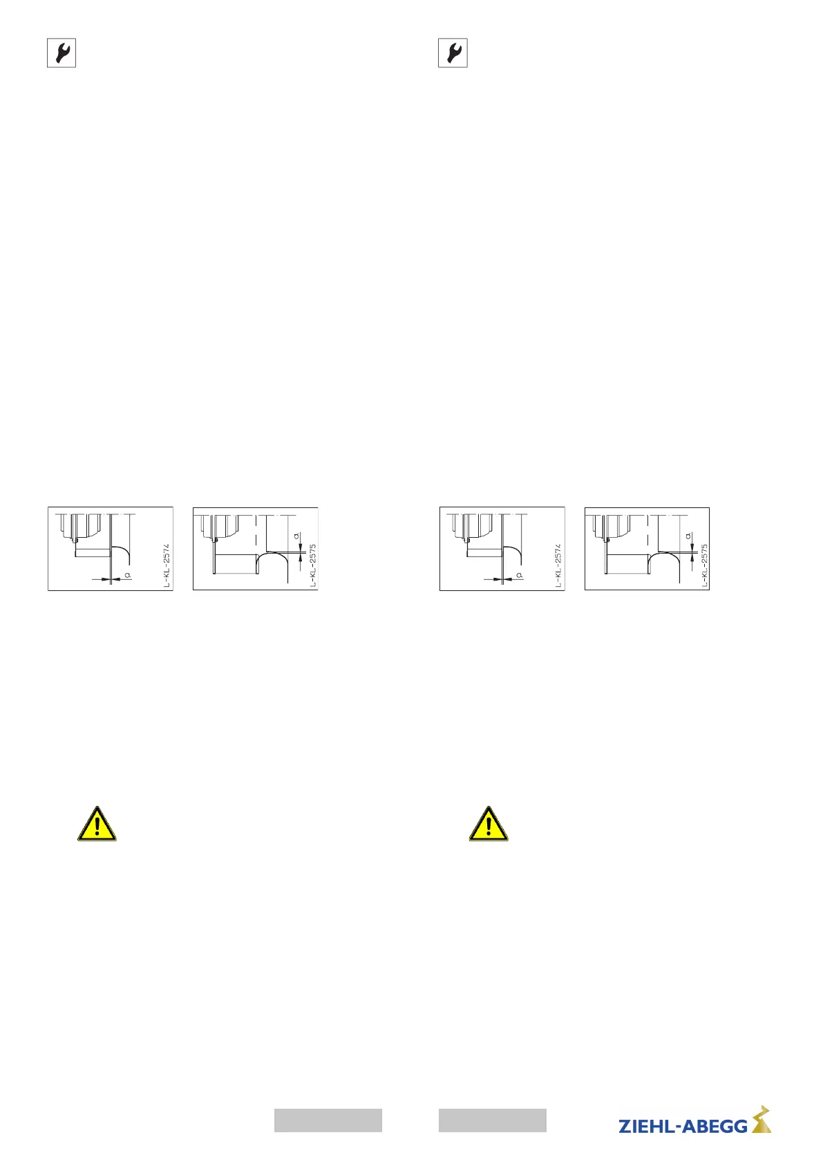
– Ensure that the clearance (gap) "a" see fig. between the
fan impeller and the stationary housing section is
constant. Distortion due to uneven surface may lead to
fan failure.
– Protective measures must be taken against falling parts
when mounting with a hanging rotor.
– In the case of a vertical motor axis, the respective lower
condensation drain hole must be open (does not apply
to protection class IP55 fans).
– Motor frame size 068: The condensation drain-holes
are attached dependent on the installation position or
application. Please supply information about this in the
product-specific ordering texts. Make sure the conden-
sation drain-holes are not blocked!
– Connect fan only to electrical circuits that can be
disconnected with an all-pole isolating switch.
– Electrical connection according to connection diagram
a) in terminal box b) in cable model connection diagram
on cable or fan enclosure
–
Do not use metal compression-gland
fittings with plastic terminal boxes. - Danger
of an electric shock if connection is not
made correctly!
– Use a dummy plug seal for the compression-gland
fitting as well.
– Only use lines which can guarantee a permanent seal
around the cable glands (pressure-resistant, dimension-
ally-stable, round-centred jacket; e.g. by means of
gusset filling)!
– Depending on the type of cable gland, attach a water
drain sleeve or use a sealing compound.
– Starting torque for screw on covers, Plastic version 1.3
Nm, Metal version 2.6 Nm
– Secure fan connection cable with cable fasteners or
cable clips.
•
Depending on the model the motors
•
can be equipped with PTC's, internally connected thermal
contacts, lead-out thermal contacts or without thermal
protection.
Connect them as below:
Montaj
Pervane, vantilatör veya balans ağırlığını gevşetme. Montajı
ve elektrik bağlantısını yalnızca bırakın
eğitimli uzman personel.
Koruyucu eldiven ve ayakkabı giyin!
•
Sisteme ilişkin montaj ve emniyet uyarılarının geçerli
standartlar ve yönetmelikler (DIN EN ISO 12100 / 13857)
ile aynı doğrultuda olup olmaması, tamamen sistemin veya
tesisin üreticisinin sorumluluğundadır.
– RE, RH, RM yapı tipine sahip fanları sabit motor
flanşlarına tespit etmek için 8.8 dayanıklılık sınıfına
sahip cıvatalar kullanın ve uygun bir cıvata emniyeti
takın. Müsaade edilen sıkma torkları: M4 = 2,1 Nm; M6
= 9,5 Nm; M10 = 40 Nm; M12 = 70 Nm; DIN EN ISO
4014 standardına, sürtünme katsayısı µ µ
top
= 0,12’ye
uygun cıvatalar bağlamında
– Motor çerçevesi boyutu 068 belirtilen vidalama
derinliğini dikkate alın.
– Donatı parçalarına sahip olmayan RZ, RK yapı tipi
fanlar, cihaz üreticisinin verilerine göre boş aks uçlarına
tespitlenir
– RG, RF, RD, RA yapı tipi fan, gövde yapı tipine göre
flanşa veya L tipi montaj braketine tespitlenir. Cıvata
bağlantılarına uygun cıvata emniyeti takılmıştır.
•
Fanların tüm yapı tipleri için şu hususlar geçerlidir:
– Gergin bir şekilde monte etmeyin. Flanş ve L tipi montaj
braketi, aynı hizada olmalıdır.
– Resimde gösterilen „a“ aralığının her yerde eşit
olmasına dikkat edin. Düz olmayan dayanma yüzeyi
nedeniyle oluşan gerilme, pervanenin sürtünmesine ve
fanın devre dışı kalmasına neden olabilir.
– Asılı rotorla montaj yapılırken düşen parçalara karşı
koruyucu önlemler alınmalıdır.
– Dikey motor aksında, altta bulunan kondens suyu deliği
açılmış olmalıdır (Koruma sınıfı IP55 olan fanlar için
geçerli değildir).
– Motor çerçevesi boyutu 068: Kondens suyu delikleri,
montaj konumuna veya kullanım durumuna bağlı olarak
açılmaktadır. Konuyla ilgili detaylı bilgiler ürüne özel
sipariş metinlerinde verilmektedir. Kondens suyu
deliklerinin kapatılmamasına dikkat edin!
– Cihaz, sadece tüm kutuplardaki akımı kesen bir şalter
ile kesilebilen bir akım devresine bağlanabilir.
– Devre şeması uyarınca elektrik bağlantısı a) Terminal
kutusunda b) Kablo tipi devre şemasında kabloda veya
fan gövdesinde
–
Plastik terminal kutularında dişli metal tapa
burçları kullanmayın; yanlış bağlantıda
yapılması halinde elektrik çarpabilir!
– Kör tapanın contasını dişli tapa burcu için de kullanın.
– Sadece vidalı bağlantılarında sürekli bir yalıtkanlık
temin eden kablolar kullanın (basınç ve form dayanımlı,
merkezi-yuvarlak kılıf; örn. dolgu malzemesi aracılığı
ile)!
– Kablo girişinin tipine bağlı olarak su tahliye dirseği takın
veya sızdırmazlık kiti kullanın.
– Kapaktaki vidalı bağlantılar için sıkma torkları: Plastik
model için 1,3 Nm, metal model için 2,6 Nm
– Fan bağlantı kablosunu kablo bağları aracılığıyla
koruma ızgarasına veya motor desteklerine tespit edin.
•
Modele bağlı olarak motorlar
•
rezistörler, dahili olarak bağlanmış termik şalterler, dışarı
alınmış termik şalterler ile veya termik korumalar olmadan
donatılmış olabilir.
Bu koruma elemanları şu şekilde bağlanmalıdır:
•
Rezistör, rezistör tetikleme ünitesine.
5
Türkçeenglish
00280351-GB-TRL-BAL-005-TR-1939-Index 014

 Loading...