Page 62 MS - SOUND decoders MS440 to MS990 and MN - NON-SOUND decoders MN170 to MN340
rot
schwarz
blau
gelb
weiss
Lötpad FA1
zur Schiene
rechts
links
Stirnlampen
hinten vorne
z.B.
Innenbeleuchtung
7 Installation and connection of the ZIMO decoder
Separate rail connections from motor connections!
All direct connections in the original locomotive design between current collectors (wheels or rail wipers)
and the motor must be reliably separated from each other; otherwise, the motor end stage may get
damaged at power-up. The same goes for the headlights and other additional accessories, which
must be completely isolated.
Interference suppression components = motor control malfunctions?
Yes, sometimes!
Explanation: Motors of model railroad locomotives are often equipped with choke coils and capacitors,
which are supposed to suppress or filter out electric noise caused by sparks arcing across the motor’s
brushes (causing poor TV reception etc.).
Such components impair the motor regulation. Compared to others, ZIMO decoders manage quite well
and there is hardly a difference in performance with or without those components in place.
Typical problems and their fixes:
ROCO, BRAWA, HORNBY – usually no problems, no action required.
FLEISCHMANN H0 – with old round motor – choke coils are no problem; capacitors should be removed,
especially the ones between the frame and motor (may destroy the decoder if left in place)!
Newer Bühler motors – no problems so far.
TRIX H0 – choke coil between track and decoder plug should be removed!
MINITRIX, FLEISCHMANN PICCOLO – very inconsistent; removing capacitors is often advantageous;
choke coils on the other hand presented no problems so far.
Indicators of such components having a harmful effect are:
- generally unsatisfactory motor control, jerking when driving slowly,
- slow/weak corrections, the (large) choke coils could be to blame,
Remedy: Bridge (or remove) the choke coils with jumpers! Remove the capacitors. However, capacitors
rarely have a negative influence.
Interference suppression components = overcurrent shutdown?
Some loco boards from PIKO up to 2019 and other manufacturers installed such large capacitors be-
tween the motor connections that severely impede operation or even cause an overcurrent shutdown.
Remedy: The "harmful" capacitor on the PIKO locomotive circuit board is usually marked "C4" and
must be removed. Normally, the locomotive circuit board has to be removed for this, because the ca-
pacitor is fitted on the underside.
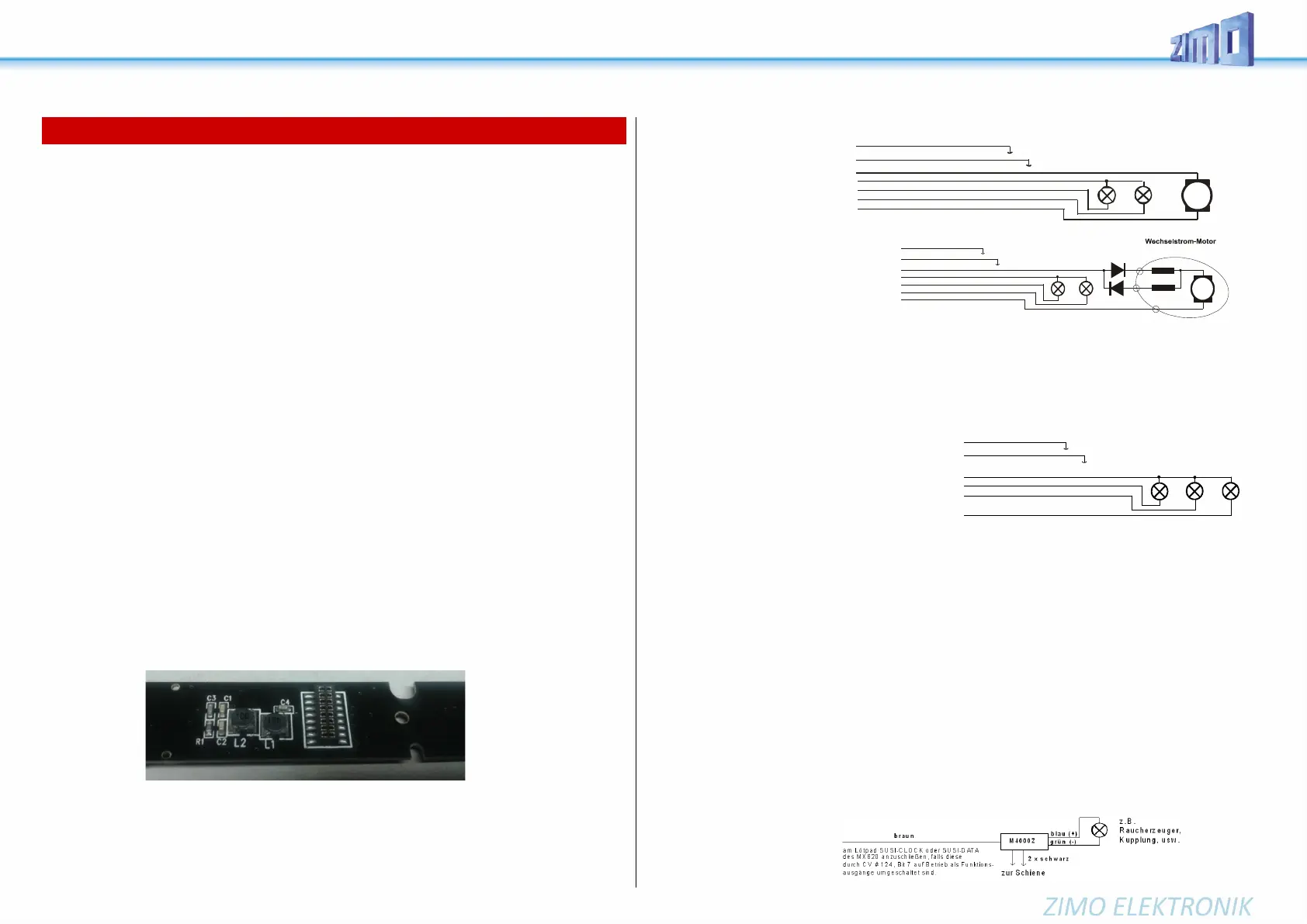
DC and AC Motors
This is the most common cir-
cuit diagram for installation in
HO models, the wire colors ap-
ply to all wired decoders (ZIMO
and third-party products)
Two additional 1N4007 diodes (or
equivalent – min 1 A) are required as
shown in the diagram below
when installing a decoder in a loco
equipped with an AC motor (usually
older Marklin or Hag engines). They
can be obtained at your local elec-
tronic store.
Most locomotives with AC motors get the power supplied by a third rail, which is of no significance as
far as the motor hook-up is concerned. The above schematic is therefore valid for AC locomotives run-
ning on two or three rail track (instead of “right rail” and “left rail” think “outside rails” and “center rail”).
Function outputs FO1, FO2, FO3, FO4 ...:
The function outputs (i.e. FO1, FO2 ...) are wired
in the same way as the headlight outputs. By de-
fault, FO1, FO2, etc. are to be switched with cab
keys F1, F2, etc. Function mapping begins with CV
#33, etc.
Using logic level outputs:
In addition to the "normal" amplified function outputs, the MS and MN decoders also have so-called
"logic level" outputs. Since these outputs are not amplified in the decoder, they provide 0 V voltage level
for output and 3.3 V voltage level for input. Most logic level outputs alternatively use the connections of
SUSI-Clock and SUSI-Data. These are converted to logic level outputs by CV #124, bit 7 = 1 (SUSI is
then no longer present). Some decoders have additional outputs besides the SUSI outputs (e.g.
MN180N18 and MS590N18), which can only be used as logic level outputs. With the MN decoders, the
logic level outputs can be loaded with max. 0.5 mA, with the MS decoders, the logic level outputs can
be loaded with max. 1.5 mA.
In order to be able to use the logic level outputs for consumers (digital couplers, smoke generators, light
bulbs, LEDs), they must be amplified. This can be done with the ZIMO amplifier module M4000Z, a NPN
transistor with a resistor at the base or a N-channel MOS-FET.
For an LED that does not require much current, e.g. because it does not have to shine very brightly,
amplification of the logic level output is not absolutely necessary. In this case the LED can be connected
together with a series resistor to the logic level output (= positive pole) and to the ground of the decoder.
The brown wire of a M4000Z amplifier module is connected with the logic level output of the decoder.
rot
schwarz
orange
blau
gelb
weiss
grau
zur Schiene
rechts
links
M
Stirnlampen
hinten vorne
Feldspulen
2 Dioden 1N4007
Rotor
Red
Black
Orange
blue
Yellow
White
Gray
Right rail
Left rail
M
Headlights
Rear Front
DC Motor
Right
Left
 Loading...