Non-Sound Decoder MX600 - MX634 and Sound Decoder MX640 - MX658 Page 17
0
10
20
30
40
50
60
70
80
90
100
110
120
130
140
150
160
170
180
190
200
210
220
230
240
250
0 20 40 60 80 10 0 150 200 252
D
e
f
a
u
l
t
c
o
m
p
e
n
s
a
t
i
o
n
c
u
r
v
e
C
V
#
5
8
=
2
5
5
,
C
V
#
1
0
u
n
d
#
1
1
3
=
0
F
u
l
l
c
o
m
p
e
n
s
a
t
i
o
n
a
t
l
o
w
s
p
e
e
d
,
d
r
o
p
p
i
n
g
o
f
f
t
o
0
a
t
f
u
l
l
s
p
e
e
d
.
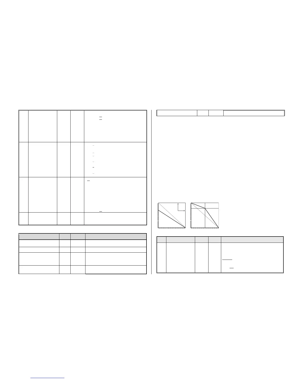
Comp. influence
Int. s peed step
A
l
t
e
r
e
d
c
o
m
p
e
n
s
a
t
i
o
n
c
u
r
v
e
C
V
#
5
8
=
1
8
0
,
C
V
#
1
0
u
n
d
#
1
1
3
=
0
R
e
d
u
c
e
d
c
o
m
p
e
n
s
a
t
i
o
n
o
v
e
r
t
h
e
w
h
o
l
e
s
p
e
e
d
r
a
n
g
e
.
0
10
20
30
40
50
60
70
80
90
100
110
120
130
140
150
160
170
180
190
200
210
220
230
240
250
0 20 40 60 80 100 150 200 252
D
e
f
a
u
l
t
c
o
m
p
e
n
s
a
t
i
o
n
c
u
r
v
e
A
l
t
e
r
e
d
c
o
m
p
e
n
s
a
t
i
o
n
c
u
r
v
e
C
V
#
1
0
=
1
2
6
,
C
V
#
1
1
3
=
2
0
0
,
I
n
c
r
e
a
s
e
d
c
o
m
p
e
n
s
a
t
i
o
n
i
n
t
h
e
m
e
d
i
u
m
s
p
e
e
d
r
a
n
g
e
.
Typical test values against jerky driving:
CV #9 = 55 (default) 83, 85, 87, ...
CV #9 = 55 (default) 44, 33, 22, …
= 255 - 178: Low frequency (for old motors only!) –
PWM according to formula (131+ mantissa*4) *2exp. Bit 0-4 is
“mantissa”; Bit 5-7 is “exp”. Motor frequency is the reciprocal of
the PWM.
Examples:
#9 = 255: frequency at 30 Hz,
#9 = 208: frequency at 80 Hz,
#9 = 192: frequency at 120 Hz.
Special ZIMO
configuration bits
4 =
00000100
with Bit 5 = 0
(20 kHz)
Bit 1 = 0: Normal acknowledgement.
= 1: High frequency acknowledgement
Bit 2 = 0: Loco number recognition OFF
= 1: ZIMO loco number recognition ON
Bit 3 = 0: 12-Function Mode
= 1: 8-Function Mode
Bit 4 = 0: Pulse chain recognition OFF
= 1: Pulse chain recognition (for old LGB)
Bit 5 = 0: 20 kHz motor control frequency
= 1: 40 kHz motor control frequency
Bit 6 = 0: normal (also see CV #29)
= 1: „Märklin brake mode
P and I value
For
BEMF motor regulation
55
medium
PID
setting
01 - 199
modified
settings
= 55: Default setting using medium PID parameters.
= 0 - 99: Modified settings for “normal” DC motors.
= 100 - 199: Modified settings for coreless motors
(Faulhaber, Maxon etc.)
Tens digit 1 - 4: Lower proportional value than default
Tens digit 6 - 9: Higher proportional value than default
Ones digit 1 - 4: Lower integral than default
Ones digit 6 - 9: Higher integral than default
Typical test values against jerky driving:
CV #56 = 55 (default) 33, 77, 73, 71, ..
EMK – Extended
sampling time
Useful initial test value: 20.
Values too small cause engine to stutter, values too big
worsens the regulation at low speeds.
Fine-tuning suggestions (if default settings are not satisfactory):
“Normal” modern Roco engine
Means high sampling rate at low load; reduced rate at
higher load to prevent loss of power.
Fleischmann “round motor”
Also recommended: CV #2 = 12, CV #147 = 60
From SW version 31: CV #145 = 2
(Attention: often helpful – remove suppressor compo-
nents.
Small coreless (Faulhaber, Maxxon
or similar)
The stronger the motor, the weaker the regulation is
set to avoid overshoots, the integral component never-
Large coreless (O gauge of larger)
theless provides for full load regulation.
Tips on how to find the optimal CV #56 settings:
Start with an initial setting of CV #56 = 11; set the engine at low speed while holding it back with one
hand. The motor regulation should compensate for the higher load within half a second. If it takes
longer than that, increase the ones digit gradually: CV #56 = 12, 13, 14...
With the locomotive still running at a low speed, increase the tens digit in CV #56. For example: (if the
test above resulted in CV #56 = 13) start increasing the tens digit CV #56 = 23, 33 ,43…as soon as
jerky driving is detected, revert back to the previous digit this would be the final setting.
Load Compensation, Compensation Curve and Experimental CV’s
The goal of load compensation, at least in theory, is to keep the speed constant in all circumstances
(only limited by available power). In reality though, a certain reduction in compensation is quite often
preferred.
100% load compensation is useful within the low speed range to successfully prevent engine stalls or
run-away under light load. Load compensation should be reduced as speed increases, so that at full
speed the motor actually receives full power. Also, a slight grade-dependent speed change is often
considered more prototypical.
Locomotives operated in consists should never run at 100% load compensation, in any part of the
speed range, because it causes the locomotives to fight each other and could even lead to derail-
ments.
The overall intensity of load compensation can be
defined with CV # 58 from no compensation
(value 0) to full compensation (value 255). Useful
values range from 100 to 200.
For a more precise or more complete load com-
pensation over the full speed range use CV #10
and CV #113 together with CV #58 to define a 3-
point curve.
Intensity of back-EMF control at the lowest speed step.
If required, an “intensity curve” can be achieved using
CV #10, 58 and 113 to reduce load regulation at higher
speeds.
Example:
# 58 = 0: no back-EMF
# 58 = 150: medium compensation,
# 58 = 255: maximum compensation.