Page 22 Non-Sound Decoder MX618 - MX634 and Sound Decoder MX640 - MX648
3.11 DC Brake Sections, “Märklin brake mode”
These are the “classic” methods of automated layout control or stopping at a “red” signal. The re-
quired settings for ZIMO decoders are spread over several CV’s.
Single Bits in each of
these CV’s are
responsible for the
correct reaction to the
DC and Märklin brake
sections.
When using track polarity dependent DC brake
sections set
CV #29, Bit 2 = “0” and CV 124, Bit 5 = “1”!
For polarity independent DC braking (Märklin brake
sections) set
CV #29, Bit 2 = “0” and CV 124, Bit 5 = “1” and
additionally CV #112, Bit 6 = “1”!
3.12 Distance controlled stopping –
Constant stopping distance
After the type of constant stopping method has been selected with CV #140 (= 1, 2, 3, 11, 12, 13)
the stopping distance will be kept as close as possible to the one defined in
CV #141,
independent of the current speed at the start of the braking sequence.
This method is especially suitable in connection with automated stops in front of a red signal with the
help of the signal controlled speed influence (ZIMO-HLU) or the asymmetrical DCC-signal (Lenz-
ABC). CV #140 is set for this purpose to 1 or 11.
Although of lesser practical value, distance controlled stopping for manual driving can also be acti-
vated (by programming CV #140 with appropriate values of 2, 3, 12, or 13), which is executed when-
ever the speed is set to 0 (by the cab, throttle, computer...).
Distance controlled
stopping
(constant stopping
distance)
Select a braking method
and braking process
Activates distance controlled stopping as per CV #141
instead of time-constant braking according to CV #4.
= 1: automatic stops with ZIMO HLU (signal controlled
speed influence) or ABC (asymmetrical DCC signal).
= 2: manual stops using the cab.
= 3: automatic and manual stops.
The start of braking is delayed in all cases above (= 1, 2
or 3) when the train travels at less than full speed, to
prevent unnecessary long “creeping” (recommended).
On the other hand:
= 11, 12, 13 same meaning as above, but braking
always starts immediately after entering the brake sec-
tion.
Distance controlled
stopping
This CV defines the “constant stopping distance”. The
right value for the existing stop sections has to be de-
(constant stopping
distance)
Distance calculation
termined by trial.
Use these figures as a starting point:
CV #141 = 255 is about 500m (500 yards) for a
real train or 6m (18 ft) in HO.
CV #141=50 about 100 m (100 yards) for a
real train or 1.2m in H0 (4 ft.).
Distance controlled
stopping
(constant stopping
distance)
High-speed correction
using the ABC method
The recognition delay (see CV #134), but also unreliable
electrical contact between rails and wheels affects stop
point accuracy more so at higher speeds than at lower
speeds. This effect is corrected with CV #142.
= 12: Default. This setting usually works fine with the
default setting in CV #134.
… compensation
using the HLU method
The HLU method is more reliable than the ABC method;
no recognition delay is usually required in CV #134; this
CV can remain at default value 0.
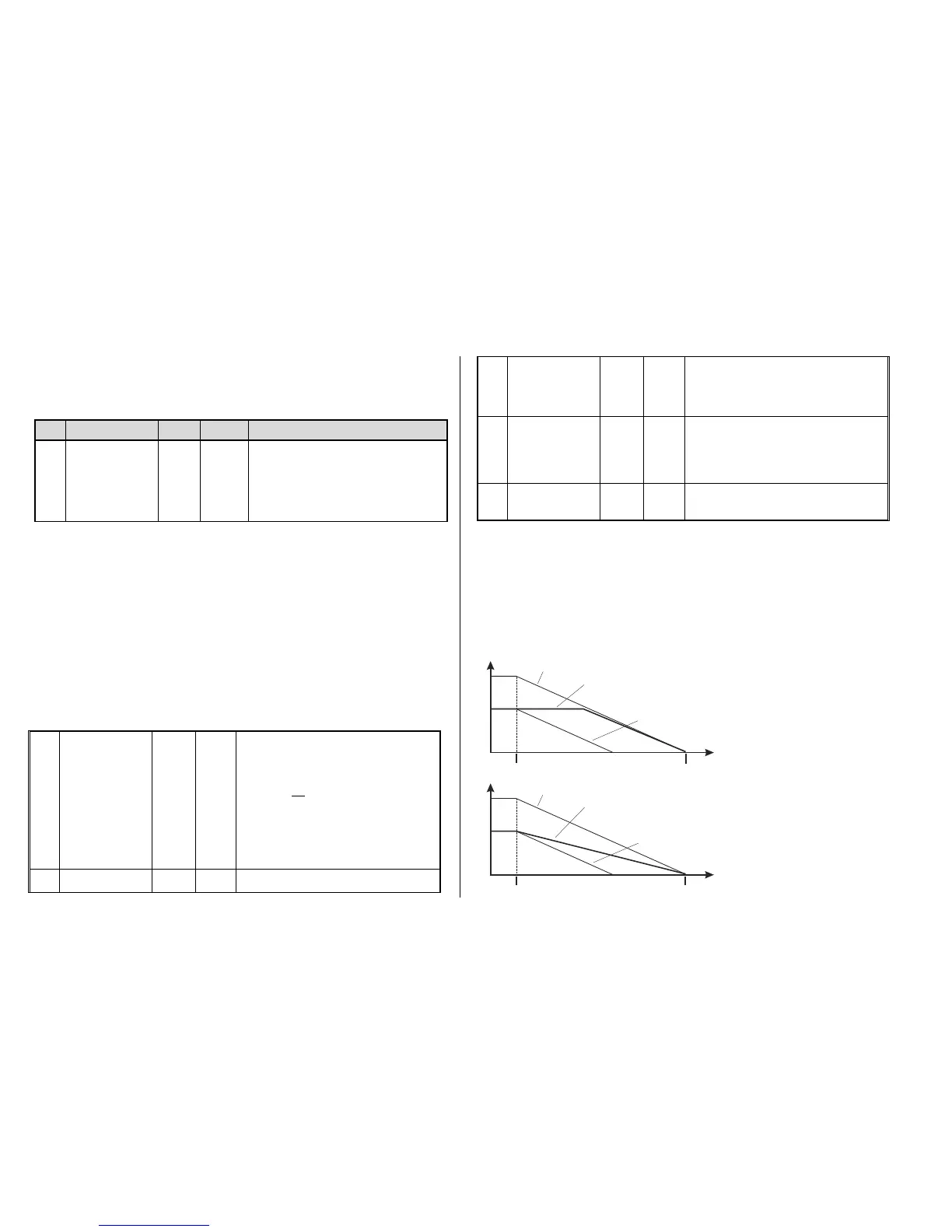
The distance controlled stopping can take place in two possible ways; see diagram below: The first is
the recommended method (CV #140 = 1, 2 ,3), where a train entering at less than full speed contin-
ues at the same speed for some time before it starts braking at a “normal” deceleration rate (same
rate as would be applied at full speed).
In the second method (CV #140 = 11, 12, 13), the train immediately starts braking when entering the
stop section, even when entering at a lower speed, which may lead to an un-prototypical behavior. It
may however be useful to use this method if used together with decoders from other manufacturers
that do not have the capability mentioned above, in order to harmonize the brake sequences.
The second method may also be the preferred method if distance controlled stopping is used manual-
ly (CV #140 = 2 or 12), so that the train reacts immediately to speed changes from the throttle.
First method for con-
stant stopping dis-
tance
Second method
for constant stop-
ping distance
Speed
Distance
Entering the stop section. Desired stop point
Deceleration starts at full speed
Deceleration starts at less than full speed,
w ith “c on s tant s to pp ing dis tan c e
train stops at desired point by automatically reducing the deceleration
v au le s in s pite of imme dia tely s tar ted s top pin g s eq ue nc e .
” programmed as CV # 140 = 11,12,13
-
The same with disabled constant stopping distance,
tr ain s tops to ea rly.
Speed
Distance
Entering the stop section.
(Or speed regulator turned to stop)
Desired stop point
Deceleration starts at full speed
Deceleration starts at less than full speed,
w ith “c on s tant s to pp ing dis tan c e
- tra in s to ps at d es ir ed po int b y au toma tic ally de la y ing s tar t of br ak in g
follo we d by “ no rmal” pr og re s sio n.
” programmed as CV # 140 = 1, 2, 3
The same with disabled constant stopping distance,
tr ain s tops to ea rly.