Large-scale Decoder & Sound Decoder MX695, MX696, MX697, MX699 Page 25
rapidly to full speed.
Bit 5 = 1: Overlapping of chuff beats
Brake key
From SW-Version
33.25
The key defined here starts a braking the engine ac-
cording to the brake time defined in CV #349 (the
normal – higher – deceleration time in CV #4 is being
ignored.
Deceleration time for
brake key
From SW-Version
33.25
For the desired effect to work, the normal deceleration
time in CV #4 must be set to a very high value (i.e.
50…250) and the deceleration time in CV #349 to a
rather low value (i.e. 5…20).
Moving the speed regulator to 0 with these settings
simulates a coasting effect while pressing the brake
key brings to engine to a rapid stop.
Compensation for
gear backlash
during direction chang-
es in order to reduce
start-up jolts
= 1 to 255: the motor spins at minimum rpm (accord-
ing to CV #2) for a specific time and only starts to ac-
celerate after this time has elapsed. This CV will only
be executed after a direction change.
How much time is required to overcome the backlash
depends on various circumstances and can only be
determined by trial and error.
Typical values are:
= 100: the motor turns about 1 revolution or a
maximum of 1 second at the minimum speed.
= 50: about ½ a turn or max. ½ second.
= 200: about 2 turns or max. 2 seconds.
Important: The minimum speed must be set correctly,
so that the motor actually turns at the speed step de-
fined as the lowest step in CV #2. Also, CV #146 is
only useful if the load regulation is set to maximum or
at least close to it (i.e. CV #58 = 200 – 255).
Note: The actual acceleration and deceleration rates for HLU brake sections
(ZIMO signal controlled speed influence) are also determined by CV #49 and #50.
Momentum – explained in more detail:
The momentum (acceleration and deceleration rates) according to CV #3 and #4 refers to the 255
internal steps which are spaced equally from 0 to full speed. The selected speed table, whether 3-
step or 28-step, does not influence the momentum behavior.
The momentum CANNOT be changed by bending the speed curve in the speed tables, but is very
much possible with the “exponential acceleration/deceleration” in CV #121 and #122.
5.8 Special Operating Mode “km/h – speed regulation“
The km/h (Kilometer per hour) speed regulation is an alternative method of driving with proto-
typical speeds in all operating situations: the cab’s speed steps (1 to 126 in the so-called “128
speed step mode”) will be directly interpreted as km/h.
However, ZIMO decoders do not simply convert the speed steps to a km/h scale but rather en-
sure that the desired speed is held, by recalculating the already traveled distance and auto-
matically make the necessary adjustments.
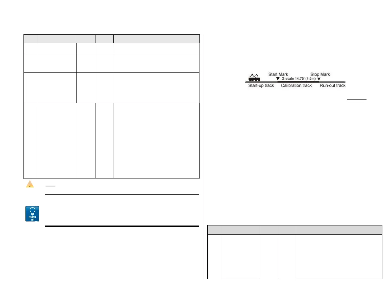
A CALIBRATION RUN must be performed with each engine:
First, we need to determine the calibration distance: a section of track that measures 100 scale
meters (plus the necessary acceleration and deceleration distances before and after), of
course without inclines, tight radii and other obstacles; for example, for HO (1:87) 115cm; for
G-scale (1:22.5) 4.5m. Mark the start and end points of the calibration section.
Step 1. Set the engine on the track, with the proper travel direction selected, about 1 to 2 me-
ters (3 – 6 ft) before the start marker and the function F0 (headlights) turned off. Ac-
celeration times (in CV #3 of the decoder as well as settings in the cab) should be set
to 0 or a very small value.
Step 2. Start the calibration mode by programming CV #135 = 1 (operations mode program-
ming). This is a pseudo-programming because the value of 1 does not replace the val-
ue already stored in CV #135.
Step 3. Set the speed regulator to a medium speed position (1/3 to ½ of full speed); the loco
accelerates towards the start marker.
Step 4. As the engine passes the start marker, turn on the function F0 (headlights); turn F0
off again when passing by the end marker. This ends the calibration run and the loco
may be stopped.
Step 5. CV #136 can now be read out for checking purposes. The calibration “result” stored in
that CV doesn’t mean very much by itself. If however, several calibration runs are per-
formed, the value in CV #136 should approximately be the same every time, even if the
traveling speed was different.
Km/h Speed Regulation in Operation:
CV # 135 controls the selection between “normal” or km/h operation:
CV # 135 = 0: The engine is controlled in “normal” mode; a possible km/h calibration run per-
formed earlier has no effect but the calibration results remain stored in CV #136.
CV #135 = 10, 20 or 5: each external speed step (1 to 126) becomes
1 km/h, 2 km/h or 0.5 km/h: see CV table below!
The speed regulation in km/h is not just useful for direct throttle control, but also for speed lim-
its through the “signal controlled speed influence” (CV’s 51 – 55). The values entered to those
CV’s are also being interpreted in km/h.
km/h –
speed regulation
activating, control and
range definition
= 0: km/h – regulation turned off; the “normal” speed
regulation is in effect.
“Pseudo-Programming” („Pseudo“ = programmed val-
ue is not being stored):
CV #135 = 1 Initiates a calibration run (see above)
Continue with “normal“ programming of CV #135 (pro-
grammed value will be stored):
= 10: each step (1 to 126) represents
1 km/h: that is step 1 = 1 km/h,