Large-scale Decoder & Sound Decoder MX695, MX696, MX697, MX699 Page 9
The following connection diagrams
are based on the MX699.
The connections on the MX696 and MX697 are placed differently, but functionally similar
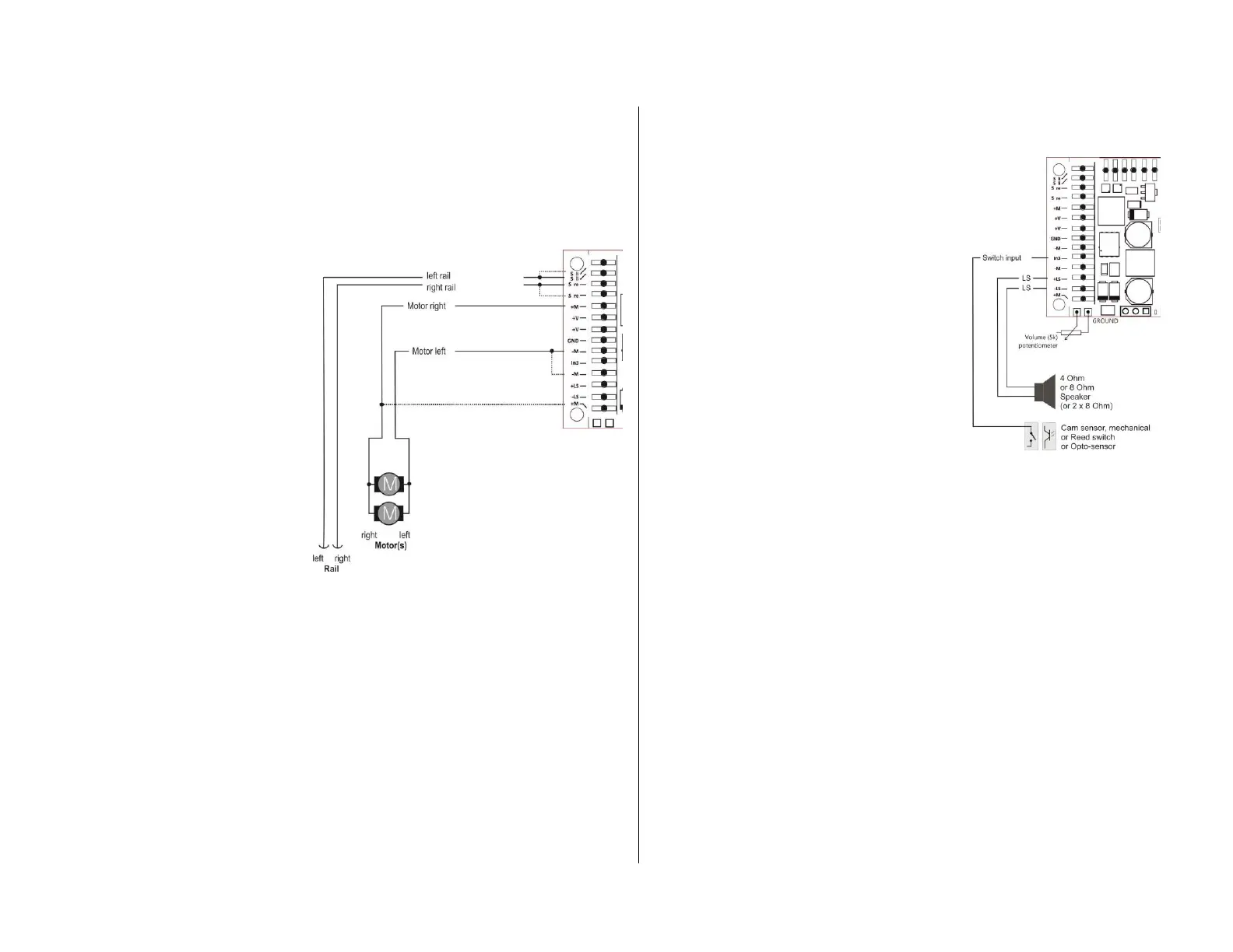
3.1 Tracks and motor(s)
The loco must provide enough
space inside, so the decoder can
be mounted without exerting me-
chanical stress.
All direct connections that are
present in the original wiring con-
figuration between the power
pick-ups (wheels and wipers) and
the motor must be insulated.
The same is important for the
headlights and other additional
accessories, which must be com-
pletely insulated.
Tracks (wheels, wipers) and mo-
tor are connected to the corre-
sponding positions on the screw
terminals (pins) according to the
picture. The second connection
points (only partly available) can,
but do not have to, be used addi-
tionally.
Generally, all DC motors used in model railways can be used.
In case, there is more than one motor in the loco, those are connected in parallel and com-
bined with each other to the decoder. A parallel connection like this ensures an automatic
alignment, provided it is an identical motor- and transmission arrangement. The MX699 usu-
ally is always strong enough to handle two or more motors.
See configuration (CVs) for motor regulation!
The connection pins for tracks and motor are available twice on the decoder, to enable send-
ing the full voltage through the relatively thin cables. For a use of up to 2 A, it is, however,
sufficient to use only one pin.
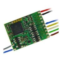
3.2 Speaker, cam sensor and volume regulation
All 4 Ohm or 8 Ohm speakers can be used,
or even some speakers connected in paral-
lel, so there is a total impedance of not
more than 4 Ohm.
The sound amplifier of the MX699 works
with 10.8V and therefore presents a sinus
power of 12 Watt onto a 4 Ohm speaker;
onto an 8 Ohm correspondingly less, i.e.
about 5 Watt.
In case, tweeters are used, they are con-
nected in parallel to the main speaker via a
frequency crossover (e.g.: a capacitor of 10
μF).
Attention: for speakers with lower specifica-
tions the volume has to be adjusted to the
processable track power.
A cam sensor (to synchronize steam chuffs
with wheel rotation) is usually not neces-
sary, because the software-provided “virtual
cam sensor” is sufficient.
In case there is a real cam sensor, a mechanical contact or a photo transistor, as well as a
Hall sensor can be connected to the switch input “IN3”. The corresponding element has to
produce a low-resistance (i.e. <10K) connection between switch input and GROUND in the
desired rotation-dependent cycle.
The volume can be controlled alternatively or additionally to the CV-configuration (see CV
#266) via the connections to an external regulator in the loco.
ONLY MX695: If such a regulator is used (100K, preferably logarithmic), the regulator on
the PCB shall be set to the highest possible volume (left limit stop), unless it is used to limit
the maximum volume to protect a lower-power speaker.
Note to the decoder MX696, MX697, MX699:
These large-scale decoders (i.e. all except the MX695) do NOT have a volume regulator
on the PCB. Nevertheless, external volume control units (potentiometers, 10K for MX697,
5K for MX699) can be connected. This is NOT possible with MX696!