AP3/30_AP3/50_AP3/80_AP3/100_Instructions. V1.01 Page 9 August / 2012
Note:Thedischargewillconsistofscaldingwaterandsteam.Asphalt,roongfeltand
non-metallic rainwater goods may be damaged by such discharges.
Note: It is not acceptable to discharge straight into a soil pipe. See G3 3.60 for guidance.
Valve outlet
size
Minimum size
of discharge
pipe D1
Minimum size of
discharge pipe D2
from tundish
Maximum resistance allowed,
expressed as a length of
straight pipe
(i.e. no elbows or bends
Resistance
created by each
elbow or bend
G1/2 15mm
22mm up to 9m 0.8m
28mm up to 18m 1.0m
35mm up to 27m 1.4m
G3/4 22mm
28mm up to 9m 1.0m
35mm up to 18m 1.4m
42mm up to 27m 1.7m
G1 28mm
35mm up to 9m 1.4m
42mm up to 18m 1.7m
54mm up to 27m 2.3m
600mm
Maximum
Pipe Length
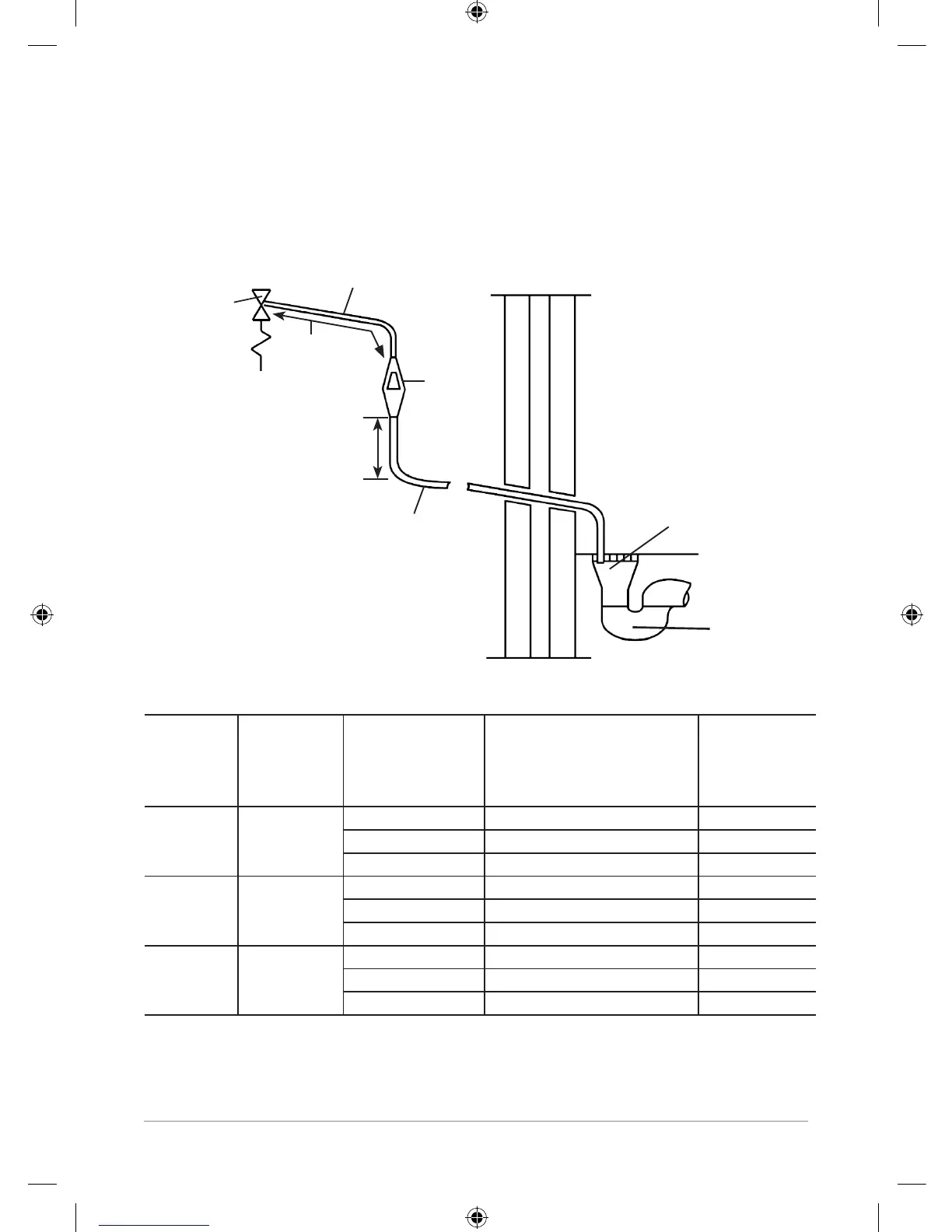
Safety device
e.g temperature
relief valve
Tundish
Metal Discharge Pipe (D2) From Tundish, with
Continuous Fall
Metal Discharge Pipe (D1) From Temperature
Relief Valve to Tundish, with Continuous Fall
Discharge Below
Fixed Grating
Trapped
Gulley
300mm
minimum
Dischargebelowxedgrating
(G3 3.62 gives alternative points
of discharge)
Note! The above chart is based on copper tube.
Plastic pipes may be of a different bore and resistance. Sizes and maximum lengths of plastic
should be calculated using data prepared for the type of pipe being used.
Diagram of a typical discharge pipe arrangement
 Loading...