Page 6 of 12 87100 v1.12 09.22 FlushMaster
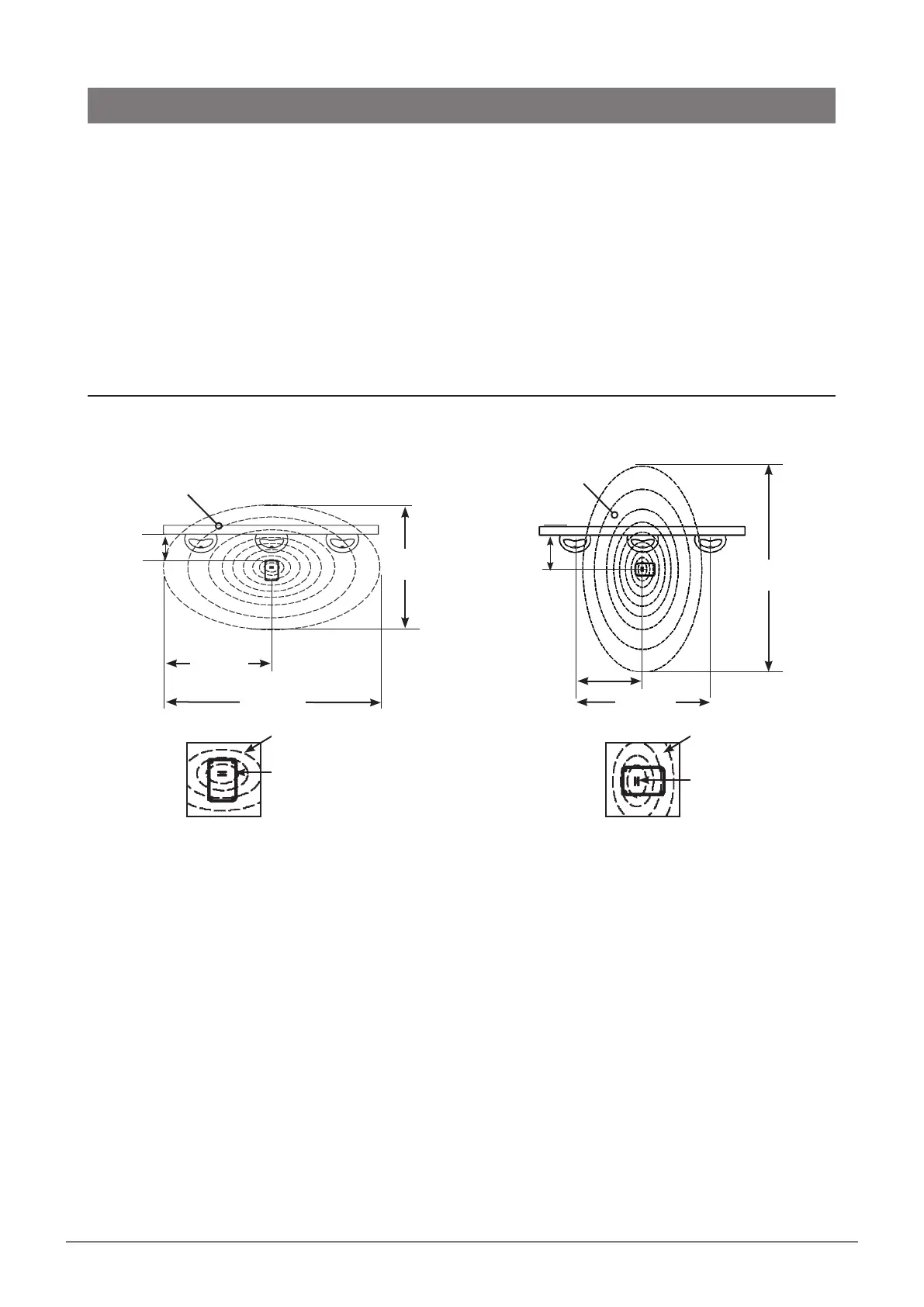
Sensor coverage from a 2700 mm ceiling is approximately 2400 x 3600 mm.
• For a single stall urinal, position the sensor above the centre of the stall.
Position the sensor slots at right angles to the urinal wall.
• For a double stall urinal, position the sensor midway between the stalls.
Position the sensor slots at right angles to the urinal wall.
• For a triple stall urinal, position the sensor above the centre of all three stalls.
Position the sensor slots parallel to the urinal wall.
• For more than three stalls, use additional sensors.
Avoid locating the sensor near heat sources (e.g. hot pipes, radiators, etc) or where direct sunlight may
fall upon the sensor lens slots.
To install the surface mounted sensor, remove the top of the sensor housing and fasten the base of the
sensor housing to the ceiling with screws and/or plugs (not provided).
If any of the cable connecting the sensor to the latching valve is visible, shield it with conduit.
Warning: Do not connect battery or power pack until all plumbing connections are completed. The
power must be connected last as connection activates the system test mode (see page 8).
Typical Installation with Surface Mounted Sensor (Model WS002)
One or two stalls
3600
mm
2400 mm
1200 mm
Two or three stalls
< 500
mm
Ceiling
Sensor
Sensor
Slots
3600 mm
1800 mm
2400
mm
Installation
2. Install sensor
Ceiling
Sensor
Sensor
Slots
Urinal wall
surface
Urinal wall
surface
< 500
mm
• Fit the air break to the top of the urinal sparge pipe (in place of a cistern), as shown in the diagram.
• Do not use sealing tape in the joints. Both the air break and the latching valve use compression
connections fittings. Sealing tape is not required.
• Supply and install a half-inch pipe from the top of the air break, to the outlet side of the latching valve.
• Securely fix the piping to the wall as per AS/NZS3500 to prevent possible tampering and vandalism.
• Adjust the timing of the flush to ensure an adequate flush, by setting the flush cycle switches on the
sensor (see page 9).