ZLAC8015 Serco Driver Manual (Special for Hub Servo Motor) V1.0 ZLAC8015 Serco Driver Manual (Special for Hub Servo Motor) V1.0
9 Shenzhen ZhongLing Technology Co.,Ltd. TEL: +86-0755-29799302 FAX:+86-0755-2912 4283 WEB: www.zlingkj.com Shenzhen ZhongLing Technology Co.,Ltd. TEL: +86-0755-29799302 FAX:+86-0755-2912 4283 WEB: www.zlingkj.com 10
3. DRIVER INTERFACE AND WIRING
3.1. INTERFACE DEFINITION
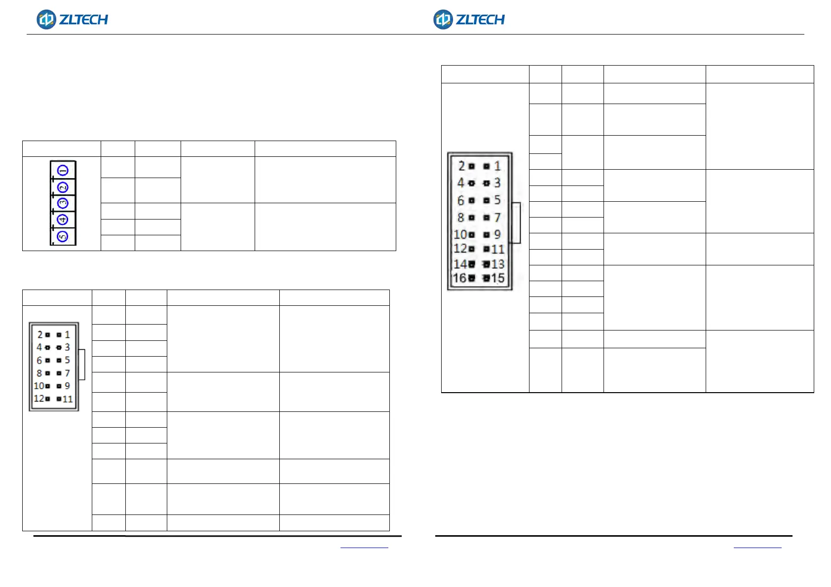
3.1.1 Power input port
Port Pin Mark Name Function
1 DC Power supply
interface
Power supply 24V-48V
2 GND
3 U
interface
Wire connected to motor
4 V
5 W
3.1.2 Encoder and Hall port
Port Pin Mark Name Function
1 iA+
Encoder
2 iA-
3 iB+
4 iB-
5 RTC+ temperature sensor
6 RTC-
7 V Hall sensor
8 W
9 U
10 GND Power ground
11 VCC Power positive Output to encoder and
HALL
12 GND Power ground
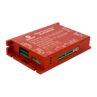
3.1.3 Control signal port
Port Pin Mark Name Function
1 B- Brake-
Brake control (5-24V)
2 BGND External power
ground
3 BDC Brake+, External
power positive
4
5 IN1+ Input 1
Could be edited via
CANOPEN or 485
6 IN1-
7 IN2+ Input 2
8 IN2-
9 OUT1+ Output Could be edited via
CANOPEN or 485
10 OUT1-
11 oB+
Encoder output
12 oB-
13 oA+
14 oA-
15 5V 5V OUT Could be used to supply
power for IN or OUT
port, output current
cannot exceed 100mA
16
GND GND