3
GAS ELECTRIC OPERATION
General Installation Instructions
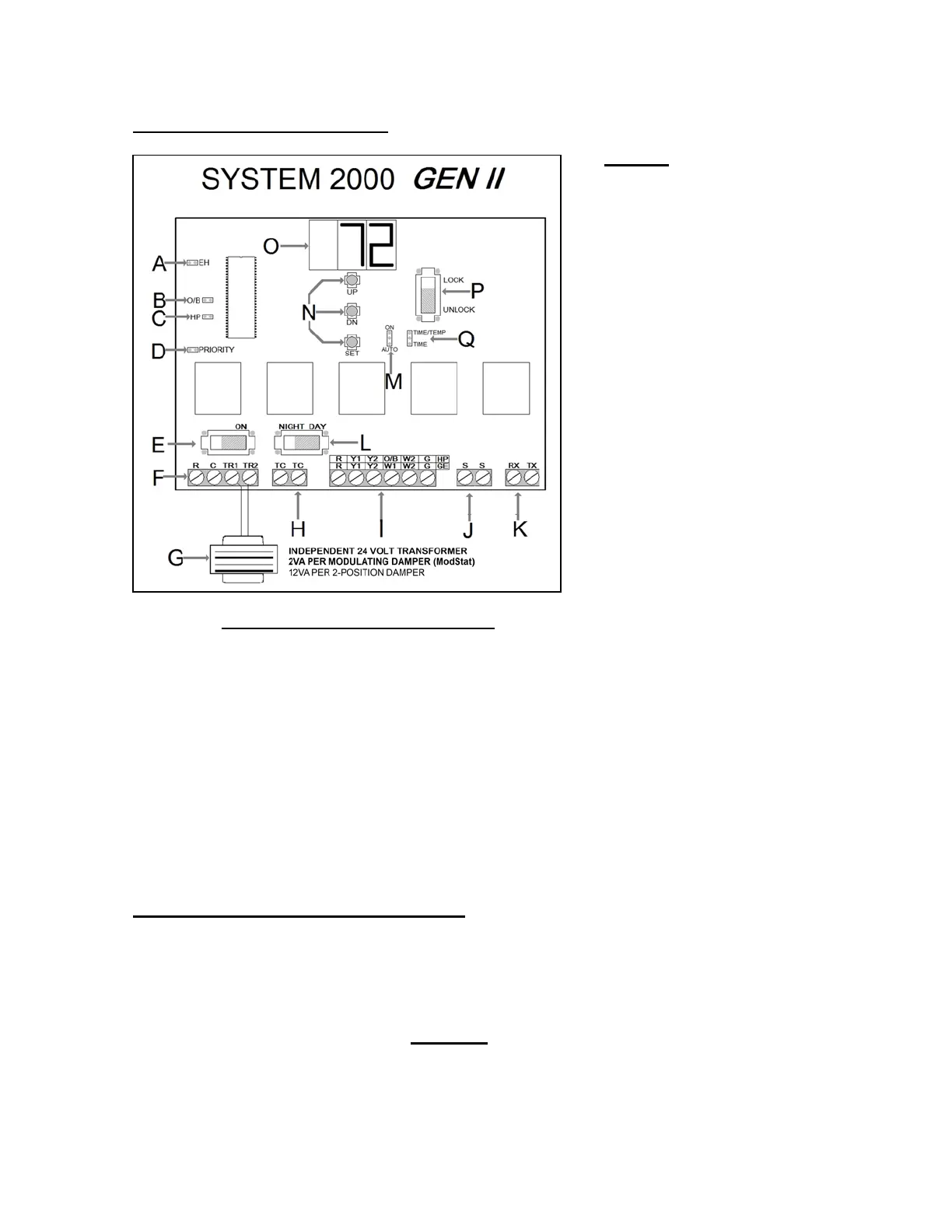
GEN II Controller
1. Install the GEN II controller on an interior wall where the ambient temperature is between 32°-
120°F (0°- 48°C) non-condensing. This controller is to be installed in an accessible interior
area; not in attics or above ceilings.
2. The controller is to be powered by a dedicated 24vac 40va transformer.
The transformer secondary is wired to TR1 TR2 on the controller (G).
The secondary
voltage to the controller must be 24 to 28vac.
A EH Jumper (Set Up Fan Operation for
Electric Heat)
B O/B Jumper (Heat Pump Only –
Reversing Valve Operation)
C H/P Jumper (Jump for Heat Pump
Operation)
D Priority Jumper (Allows for Priority Vote
Setup)
E On / Off Switch
F R C Power to ModStats (18 ga.
Thermostat wire)
G 24-Volt Transformer
H TC – TC Time Clock Terminals
I Unit Terminals
J S S Terminals – Leaving Air Sensor
(LAT)
K RX – TX Communications Wire
L Day / Night Switch
M Fan Jumper (Continuous or Auto)
N Up / Down / Set Buttons (High Limit,
Low Limit, Set)
O Digital Display (Leaving Air Temperature
and configuration)
P Lock / Unlock (Lock Thermostats)
Q Staging Strategy (Time / Temperature or
Time Only)
TERMINAL FUNCTIONS / CONNECTIONS
TX / RX – Data Transmit / Receive
S S – Leaving / Supply Air Sensor Input
G – Fan Output
W2 – Auxiliary / Emergency Heat
O/B – Reversing Valve Output
Y2 – Stage 2 Cool Output
Y1 – Stage 1 Cool Output
R – 24vac from Unit Transformer
TC / TC – Time Clock Input for Occupied /
Unoccupied Operation
TR1 / TR2 – 24vac Power Input / Common
R / C – Stat Power Daisy Chain Stat to Stat
(18 ga. Thermostat wire)