ZEBRA Timer-thermostat
v 0.V 12/170 TAGBASE 17
ES
EN
A System presentation
ZEBRA timer-thermostats are designed to work alongside
ZONING SYSTEM control units in order to control
temperature for up to 6 different zones.
The ZEBRA timer-thermostat communicates with the
control unit. The central unit manages one or several
motorised gates (which regulate the airflow), as well as
starting up/shutting down the climate control unit, which
provides the airflow.
B Technical characteristics
ZEBRA thermostat (transmitter)
• Power supply: 12 VDC
• Consumption: < 0.3 VA
• Control output: Modbus RTU Rs485
• Wiring: S <1.5 mm
2
• Operating temperature: 0ºC to 50ºC
• Storage temperature: -20ºC to 60ºC
• Humidity Range: 10-90% (no condensation)
• Wall mount with bolts (supplied)
• Protection grade: IP 20
• NTC10K Temperature sensor. Accuracy 0.1ºC
• CA control accuracy according to Standard EN15500.
CA=0.4 (Test report CLMS17-742. CSTB)
• Economy ECO mode (±3ºC setpoint temperature
variation)
• Frost protection for: T<7ºC+/-3ºC
• Dimensions (LxHxZ): 85x108x13 mm
• Weight 0.11 kg
Control unit (receiver)
• Power 230 VAC/50-60 Hz
• ZITY consumption: 6 VA.
• Work cycle <10%
• For installation up to 2000 m above sea level. Receiver,
Class III
• 230 VAC/5A relay outputs (maximum load: 5A, cos φ
=1)
• Protection grade: IP 20
• Electrical insulation protection, Class II
• Operating temperature: 0ºC to 55ºC
• Storage temperature: -10ºC to 60ºC
• Dimensions (LxHxZ): 160x90x65 mm
• Weight 0.5kg
MADEL ATD hereby declares that the ZEBRA/ ZITY
equipment complies with the essential requirements and
any other applicable or enforceable provisions of Directives
2014/35/EU LVD, 2014/30/EU EMC and 2014/53/UE RED,
2011/65/EU ROHS, 2001/95/EC General product safety,
2012/19/UE RAEE and Regulation 1907/2006 REACH.
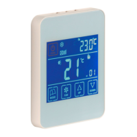
C Location of the thermostats (fig. 1)
Fig. 1 Location of the thermostats
• Place the thermostat in a prominent location.
• Place at a height of approximately 1.5 m, avoiding direct
heat sources and unwanted air currents.
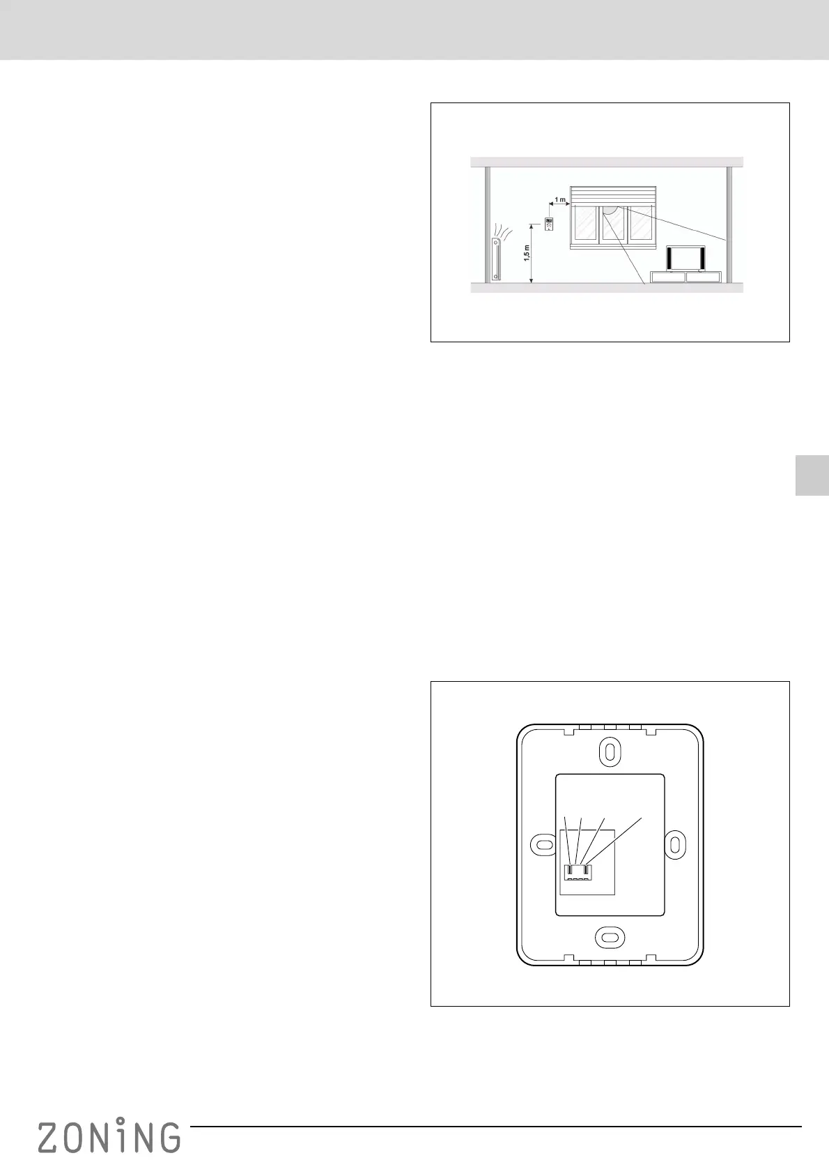
D Power supply connection (fig. 2)
The ZEBRA timer-thermostat should have a supply voltage
of 12VDC, provided by a source that is able to provide at
least 0.3VA. This power may be supplied by the ZITY
central unit.
In addition to the power supply, it has terminals A and B for
communication with the ZITY central power unit via RS485.
The power supply connector is located at the rear, as
shown in the following figure.
Fig. 2 Connections for power supply and communication
ubicacion
A B GND +12V
RS485