Connecting the Power Cables and the Grounding Cable 43
3 Check whether the RPS LED on the front panel of the switch is ON. If the LED is
ON, the 48V RPS is properly connected.
c
CAUTION:
■ Make sure that the grounding cable has been properly connected before
powering on the switch.
■ The length of the DC power cable must be less than 3 m (9.8 ft).
Connecting the DC power cable of the Switch 4800G 48-Port and Switch
4800G 24-Port-DC
The Switch 4800G 48-Port and Switch 4800G 24-Port-DC use the 48V RPS, whose
input voltage is in the range of -48 V to -60 V.
Figure 40 Appearance of the -48V RPS port
1 Connect one end of the grounding cable (delivered with the switch) to the
grounding screw on the rear panel and the other end to the ground nearby.
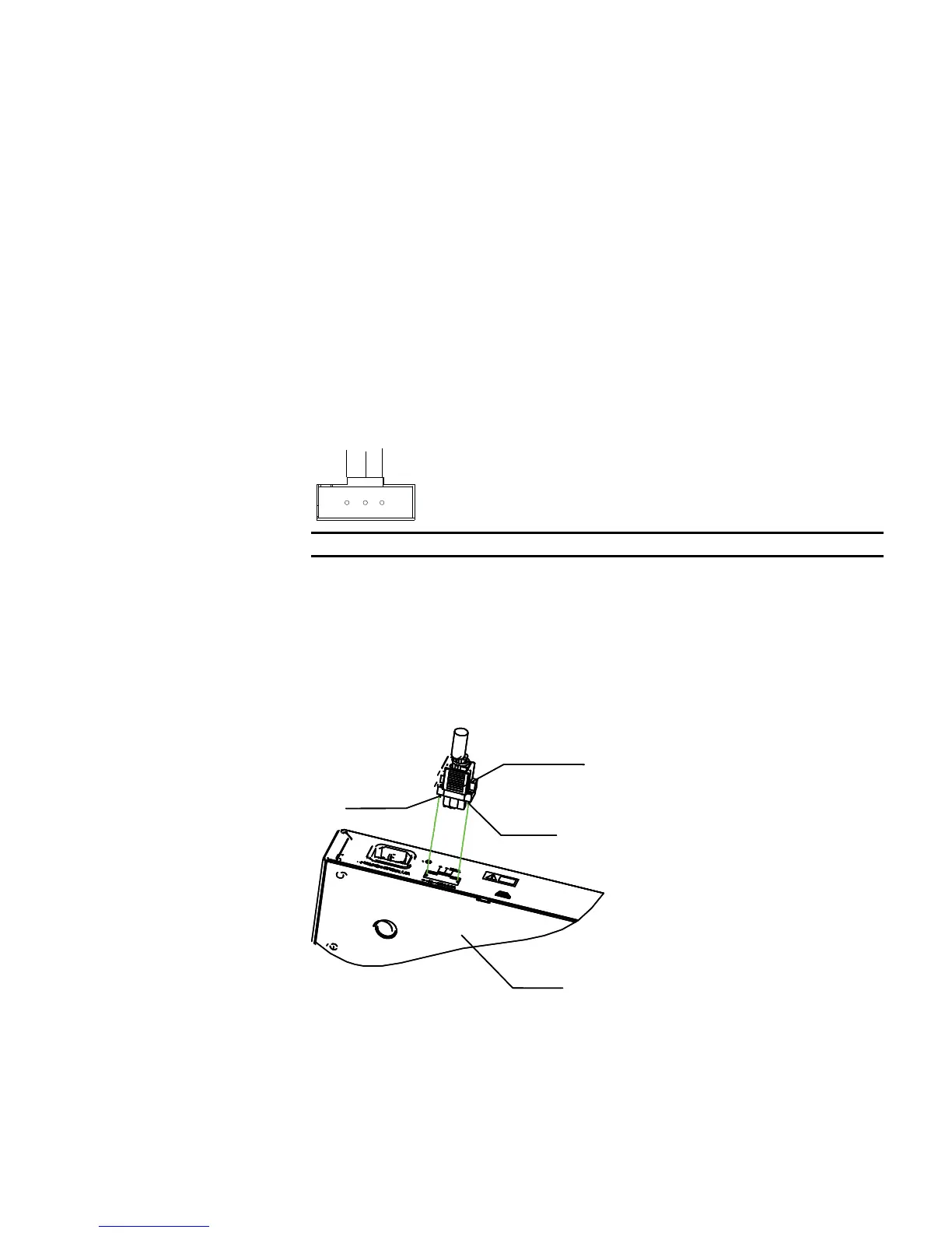
2 Connect one connector to the RPS port on the switch and use a small flat-module
screwdriver to fix the connector with two screws (delivered with the switch), as
shown in Figure 41.
Figure 41 Connect the 48V RPS connector to the chassis
3 Check whether the RPS LED on the front panel of the switch is ON. If the LED is
ON, the 48V RPS is properly connected.
c
CAUTION: Make sure that the grounding cable has been properly connected
before powering on the switch.
+: -48V (return) terminal -: Negative terminal (-48 V to -60 V) NULL: Reserved
Connector parts
Screw 1
Screw 2
Chassis
Connector parts
Screw 1
Screw 2
Chassis