48 CHAPTER 3: INSTALLING THE SWITCH
10 GE XFP Interface
Module
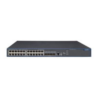
Appearance and front panel of a one-port 10 GE XFP interface module
Figure 47 Appearance of a one-port 10 GE XFP interface module
Figure 48 Front panel of a one-port 10 GE XFP interface module
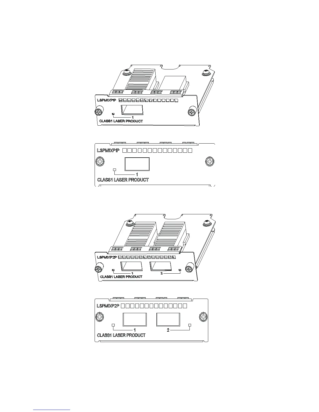
Appearance and front panel of a dual-port 10 GE XFP interface module
Figure 49 Appearance of a dual-port 10 GE XFP interface module
Figure 50 Front panel of a dual-port 10 GE XFP interface module
Installation procedure
1 Wear an ESD-preventive wrist strap and verify the ESD-preventive wrist strap is
properly grounded. Then take out the XFP interface module from the package.
2 Loosen the mounting screws of the blank panel on the read panel of the switch
with a screwdriver and remove the blank panel.