24 CHAPTER 1: INTRODUCING THE SWITCH 5500 FAMILY
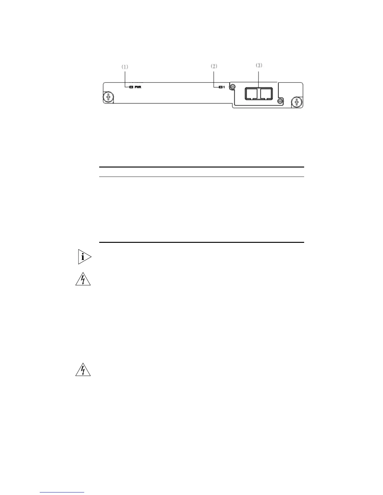
Figure 14 1-port 10 Gbps XENPAK module
The Table 7 lists the available XENPAK optical modules:
Table 7 XENPAK optical port module supported by 1-port 10 Gbps XENPAK
module
For specifications of XENPAK Transceivers, refer to 3Com’s Web site at
www.3Com.com.
WARNING: When an Expansion Module is not installed, ensure that the
blanking plate is fitted by tightening all screws with a suitable tool.
Failure to fit a blanking plate may void the product warranty.
Power Socket The Switch automatically adjusts its power setting to any supply voltage
in the range 100-240 VAC.
Open Book Warning
Labels
Before installing or removing any components from the Switch 5500
Family or carrying out any maintenance procedures, you must read the
safety information provided in
Appendix A of this guide.
AVERTISSEMENT: Avant d'installer ou d'enlever tout composant des
commutateurs de la gamme Switch 5500 ou d'entamer une procédure
(1) Module power
LED
(2) Port status LED (3) 10 Gbps XENPAK
optical/electrical port
Table 8 Type Table 9 Model
XENPAK optical module
XENPAKs that are supported
3CXENPAK91 10GBASE-LX4
3CXENPAK92 10GBASE-LR
3CXENPAK93 10GBASE-T
3CXENPAK94 10GBASE-SR
3CXENPAK95 10GBASE-CX4
3CXENPAK96 10GBASE-ER
 Loading...