21
Circuit Board Jumpers, Adjustment Controls, Indicators and Switches
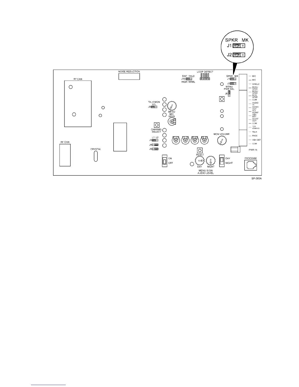
Figure 14. Base Station Circuit Board
Jumpers
J1 and J2 Set for the type of menu sign in the system. Jumper pins 1 and 2 on both jumpers for menu
signs having a speaker only. Jumper pins 2 and 3 on both jumpers for menu signs having a
speaker and a microphone.
J3 Set to designate the number of the lane in the system. Jumper pins 1 and 2 to select lane 1.
Jumper pins 2 and 3 to select lane 2.
J4 Set for the type of vehicle detector in the system. Jumper pins 1 and 2 for an air switch
detector. Jumper pins 2 and 3 for a loop/sodar detector.
J5 Set to designate the type of communication operation. Jumper pins 2 and 3 for standard
operation. Jumper pins 1 and 2 for duplex operation.
J6 MENU PWR SEL – STD or DPLX
STD – applies power to outbound speaker amplifiers only when the TALK switch is pressed.
Note: for Standard (half–duplex) operation J6 MUST be placed in the STD position.
DPLX – applies power to outbound speaker amplifiers constantly. This will reduce the click
that is sometimes heard in duplex mode when the TALK button is pressed.
J9
TALK MON LVL
REDUCE – reduces the volume to the Monitor Speaker by 16dB while TALK is activated.
This decreases the chance of feedback when a headset is operating near the Monitor Speaker in
duplex mode.
FULL – unreduced volume to monitor speaker in all modes.
*Note
This setting may cause feedback when a headset is operating near the monitor
speaker in duplex mode.