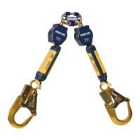
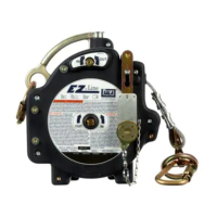
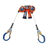
The provided manual details the procedure for replacing the shock pack cover on a NANO-LOK EDGE Self-Retracting Device (SRD), a component designed for fall protection. This document serves as a user instruction manual, specifically for the "Shock Pack Replacement" (5908483 REV. A).
Function Description:
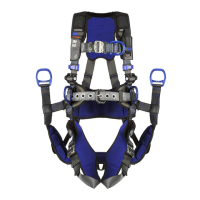
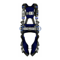
The NANO-LOK EDGE SRD is a fall protection device, and the shock pack cover is an integral part of its design. The primary function of the shock pack cover is to enclose and protect the internal energy absorber. The internal energy absorber is a critical safety component that deploys during a fall arrest event, dissipating the energy generated by the fall to reduce the impact forces on the user. The cover ensures that the energy absorber remains clean, free from damage, and properly contained within the device, thereby maintaining the SRD's effectiveness and reliability in a fall arrest scenario. The cover also contributes to the overall structural integrity and aesthetic presentation of the device.
Usage Features:
The manual outlines a clear, step-by-step process for both removing an old shock pack cover and installing a new one. This procedure is intended to be performed by users or competent persons who have already inspected the SRD according to its primary user instruction manual.
Shock Pack Cover Removal (Section 1.0):
- Tool Requirement: The process begins by requiring a thin, flat, non-sharp tool, such as a ruler, marked at 2.5 inches from one end. This specific tool is crucial for safely manipulating the webbing within the shock pack without causing damage.
- Positioning: The shock pack is placed on a flat surface with its back side (without labels) facing up, ensuring proper orientation for the procedure.
- Tool Insertion: The marked end of the tool is inserted between two layers of webbing at a specified location (Figure 4A) and slid until it reaches the 2.5-inch mark (Figure 4B). This action is designed to disengage internal hook and loop materials.
- Disengagement Technique: The tool is then slid left and right within the shock pack to further detach the internal hook and loop fasteners, which secure the webbing.
- Web Strap Extraction: With the tool still in place, the web strap (6A) is gently guided out of the shock pack cover's opening (6B).
- Further Disassembly: The end of the web strap (7A) is pulled from under the round bar (7B) of the interface.
- Cover Removal: The shock pack cover, now loose, is alternately pulled from each leg until it completely detaches from the internal energy absorber.
- Post-Removal Inspection: After the cover is removed, a critical inspection of the internal energy absorbers (Figure 9.9) is required. This inspection checks for:
- Damage to the tear web (B) and its containment within the two shrink tube pieces (A).
- Damage to the stitch pattern (E).
- Intact black plastic collar (C) and rivet (D).
- A clear directive is given to dispose of the Nano-Lok Edge SRD if it has been subjected to fall arrest forces or if inspection reveals unsafe or defective conditions. Disposal involves cutting the cable lifeline in half or otherwise disabling the SRD to prevent inadvertent use.
New Shock Pack Cover Installation (Section 2.0):
- Pre-Installation Inspection: Before installing a new cover, the SRD must pass a general inspection, and the internal energy absorbers must have passed the inspection detailed in Section 1, Step 9.
- Initial Positioning: The new shock pack cover is placed on a flat surface with its logo side down, alongside the SRD assembly, with the interface buttons facing down. This ensures correct orientation for assembly.
- Energy Absorber Insertion: The ends of the internal energy absorbers are inserted into the sleeve of the new cover (2A). The cover is then pulled over the internal energy absorbers, feeding the two legs into separate pockets (2B).
- Web Strap Re-insertion: Once the cover is pulled up to the interface (3A), the web strap (3B) is slid back into the sleeve of the cover, specifically under the round bar of the interface (3C).
- Tool-Assisted Web Strap Placement: The same tool used for removal is inserted into the pocket on the end of the web strap.
- Guiding the Web Strap: With the tool still in the pocket, both the web strap and the tool are guided inside the sleeve of the shock pack cover.
- Full Insertion: The tool and web strap are pushed into the shock pack cover until the tool reaches the 2.5-inch mark, indicating the web strap is fully inserted.
- Securing the Web Strap: The tool is removed, and the material above the web strap is pressed down firmly to engage the hook and loop material, locking the web strap in place.
- Final Verification: The SRD unit is flipped over to verify that the internal energy absorber is fully concealed by the new shock pack cover and that the shock pack cover logo and the connector buttons of the interface are facing the same direction.
Maintenance Features:
The manual implicitly highlights several maintenance features through its detailed instructions:
- Component Replacement: The entire procedure is a maintenance task, allowing for the replacement of a worn or damaged shock pack cover without needing to replace the entire SRD, provided other components are in good condition. This extends the lifespan of the SRD and reduces waste.
- Detailed Inspection Points: The manual emphasizes critical inspection points for the internal energy absorber during the cover replacement process. This includes checking the tear web, shrink tube pieces, stitch pattern, plastic collar, and rivet. These inspections are crucial for ensuring the continued safety and functionality of the SRD.
- Clear Disposal Guidelines: The instruction to dispose of the SRD if it has been subjected to fall arrest forces or if inspection reveals unsafe conditions is a key maintenance directive. This prevents the re-use of compromised equipment, enhancing user safety. The method of disabling the SRD (cutting the lifeline) before disposal is also a critical safety measure to prevent accidental re-use.
- Tool-Assisted Procedures: The use of a specific, non-sharp tool for manipulation minimizes the risk of damage to the delicate internal components during maintenance, promoting careful handling and extending component life.
- Orientation and Alignment Checks: Throughout the installation process, specific instructions are given for correct orientation (logo side down, buttons facing down) and final alignment verification. These steps ensure that the shock pack cover is installed correctly, which is vital for the proper function and aesthetics of the SRD.
- Emphasis on Pre-Procedure Inspection: The requirement that the rest of the SRD must pass inspection before proceeding with the cover replacement underscores a holistic approach to maintenance, ensuring that all parts of the device are in safe working order.
In summary, this manual provides comprehensive instructions for a specific maintenance task on the NANO-LOK EDGE SRD, focusing on safety, proper technique, and thorough inspection to ensure the continued reliability and performance of the fall protection equipment.