Do you have a question about the 3M DBI SALA Pro Series and is the answer not in the manual?
Highlights critical safety warnings and potential consequences of misuse.
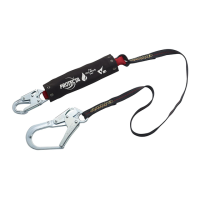
Provides specific precautions to mitigate risks when using energy absorbing lanyards.
Emphasizes critical warnings and potential outcomes of improper use.
Lists specific safety precautions for work positioning and travel restraint applications.
Provides essential safety measures for elevated work environments.
Emphasizes the need for trained personnel to install and use the equipment.
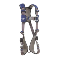
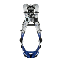
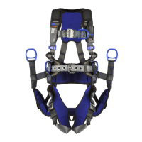
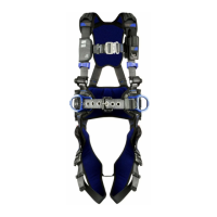
Mandates the use of a full body harness and proper connection points.
Details essential checks to perform before each use of the lanyard.
Instructs on immediate actions and service removal after a fall.
Defines the required frequency for user and competent person inspections.
Specifies actions to take when defects or unsafe conditions are found.
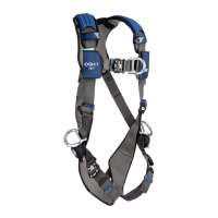
This document provides comprehensive information regarding the 3M™ DBI-SALA® Pro Series Lanyards, which are designed for fall protection in various work environments. The lanyards are categorized into different models, each with specific features and applications, and are compliant with ANSI Z359.13, ANSI Z359.3, OSHA 1910.140, and OSHA 1926.502 standards.
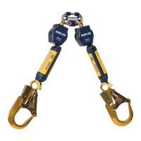
The Pro Series Lanyards serve as a critical component of a personal fall protection system. They are primarily intended for Restraint or Work Positioning applications, preventing users from reaching or being exposed to a fall hazard. Energy-Absorbing Lanyards, which include an integral energy absorber, can also be used for Fall Arrest applications, mitigating the forces experienced during a fall. Twin Leg Lanyard models are designed for 100-percent tie-off, allowing continuous fall protection while moving between anchorage points. The lanyards connect the user's harness to an anchorage point or structure, with the energy absorber end always attaching to the harness for Fall Arrest systems.
The lanyards come in various lengths (L) and widths (W), depending on the model. For instance, models like 1340040, 1340125, and 1340200 are 6.0 ft (1.83 m) long, with widths of 1.75 in (4.45 cm) or 1.95 in (4.95 cm). Shorter lanyards, such as 1341002, are 3.0 ft (0.91 m) long. The materials used include Web - Polyester, Web - Elastic Polyester, Cable - Galvanized, and Nylon Rope.
Energy absorbers are integrated into specific models, indicated by "Shock Pack" or "Tubular Web" in the "Energy Absorber" column of Table 1. The capacity of these lanyards is for one person with a combined weight (including clothing, tools, etc.) within the range of 130 lb. to 310 lb. (59 kg to 140 kg). The average arresting force is 900 lbf (4.0 kN), and the maximum free fall is 6.0 ft (1.83 m).
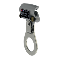
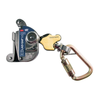
Connector specifications vary by model. Common connectors include Snap Hooks (Zinc-Plated Steel) with gate openings of 3/4 in. (19 mm) or 2-3/8 in. (60 mm), Rebar Hooks (Alloy Steel) with 2-3/8 in. (60 mm) gate openings, Rope Grabs (Steel), and Carabiners (Zinc-Plated Steel) with 1-1/8 in. (28.6 mm) gate openings. All connectors have a gate strength of 3,600 lbf (16 kN) and a tensile strength of 5,000 lbf (22.2 kN).
The Energy Absorber Deployment graph (Figure 5) illustrates free fall and deployment distance based on user weight (130 lb., 220 lb., 310 lb.). It also defines maximum allowable deployment distances (OSHA and ANSI) and maximum allowable free fall (OSHA/ANSI). For ANSI/OSHA lanyards with free fall distances of 6.0 ft (1.8 m) to 12.0 ft (3.7 m), or for user weights of 310 lb. (140 kg) to 420 lb. (191 kg), an additional 1.0 ft (0.3 m) is added to the deployment distance calculation.
This comprehensive guide ensures that users are well-informed about the proper selection, installation, operation, and maintenance of 3M™ DBI-SALA® Pro Series Lanyards to ensure safety and compliance with relevant standards.
| Brand | 3M |
|---|---|
| Model | DBI SALA Pro Series |
| Category | Security Sensors |
| Language | English |