11
1.0 APPLICATIONS
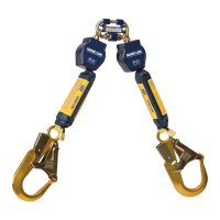
1.1 PURPOSE: Energy Absorbing Lanyards are designed to be a component in a personal fall arrest system (PFAS). They
dissipate fall energy and limit fall forces transferred to the body. Figure 1 identies the Lanyard models covered by this
instruction manual. They may be used in most situations where a combination of worker mobility and fall protection is
required (i.e. inspection work, general construction, maintenance work, oil production, conned space work, etc.).
1.2 STANDARDS: Your Lanyard conforms to the national or regional standard(s) identied on the front cover of these
instructions. Refer to the local, state, and federal (OSHA) requirements governing occupational safety for additional
information regarding Personal Fall Protection.
1.3 TRAINING: This equipment is intended to be used by persons trained in its correct application and use. It is the responsibility of the
user to assure they are familiar with these instructions and are trained in the correct care and use of this equipment. Users must also
be aware of the operating characteristics, application limits, and the consequences of improper use.
1.4 REQUIREMENTS: Always consider the following limitations when installing or using this equipment:
• Capacity: Lanyards are for use by one person with a combined weight (clothing, tools, etc.) meeting the Weight
Range specied in Figure 1 for your Lanyard Model. Make sure all of the components in your system are rated to a
capacity appropriate to your application.
• Anchorage: Anchorages selected for fall arrest systems shall have a strength capable of sustaining static loads
applied in the directions permitted by the system of at least:
1. 5,000 lbs. (22.2 kN) for non-certified anchorages, or
2. Two times the maximum arresting force for certified anchorages.
When more than one fall arrest system is attached to an anchorage, the strengths set forth in (1) and
(2) above shall be multiplied by the number of systems attached to the anchorage.
;
From OSHA 1926.502 and 1910.140: Anchorages used for attachment of personal fall arrest systems shall be
independent of any anchorage being used to support or suspend platforms, and capable of supporting at least 5,000 lbs.
per user attached, or be designed, installed, and used as part of a complete personal fall arrest systems which maintains
a safety factor of at least two, and is under the supervision of a qualied person.
• Free Fall: When there is no slack, the Lanyard will limit Free Fall Distance to 0 ft. (0 cm). Free Fall Distance changes with
lanyard slack and orientation of the Harness Connection Point to the Anchorage Connection Point (see Figure 2):
If the Harness Connection Point is below the Anchorage Connection Point (Figure 2A): FF = L
y
- HD
A
If the Harness Connection Point is above the Anchorage Connection Point (Figure 2B): FF = L
y
+ HD
A
FF Free Fall Distance
HDA Vertical Distance from the Harness Connection Point to the Anchorage Connection Point.
Ly Length of the Lanyard
;
Do not lengthen lanyards: Do not lengthen Lanyards by connecting a lanyard, energy absorber, or similar
component without consulting 3M.
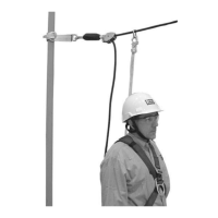
• Swing Falls: Swing Falls occur when the anchorage point is not directly above the point where a fall occurs. The
force of striking an object in a swing fall may cause serious injury (see Figure 3). Minimize swing falls by working as
directly below the anchorage point as possible.
• Fall Clearance: Figure 4 illustrates calculation of the required clearance below the Lanyard System Anchorage. Required
clearance will vary with the amount of deployment of the Energy Absorber (X
PEA
). The charts in Figure 5 graph X
PEA
based
on Worker Weight and Free Fall Distance.
To calculate Fall Clearance (C
a
): C
a
= MASD + L
y
+ X
PEA
+ X
H
+ 1.5 m (5 ft) + 0.6 m (2 ft)
Ca Clearance Below the Anchorage
MASD Maximum Anchorage System Deection
Ly Lanyard Length
XPEA Amount of Energy Absorber Deployment - See the appropriate graph in Figure 5 for your Lanyard
Type and Capacity Range. Look up Worker Weight (including clothing, tools, etc.) on the vertical
axis (horizontal grid lines). Where Worker Weight falls between grid lines, use the next grid line.
Where the Worker Weight and graph line intersect, determine Energy Absorber Deployment (XPEA)
from the horizontal axis directly below the point of intersection.
XH Estimated Harness Stretch
1.5 m (5 ft) Distance from Dorsal D-Ring to Toes
0.6 m (2 ft) Clear Margin
 Loading...