25
087-0020 REV E
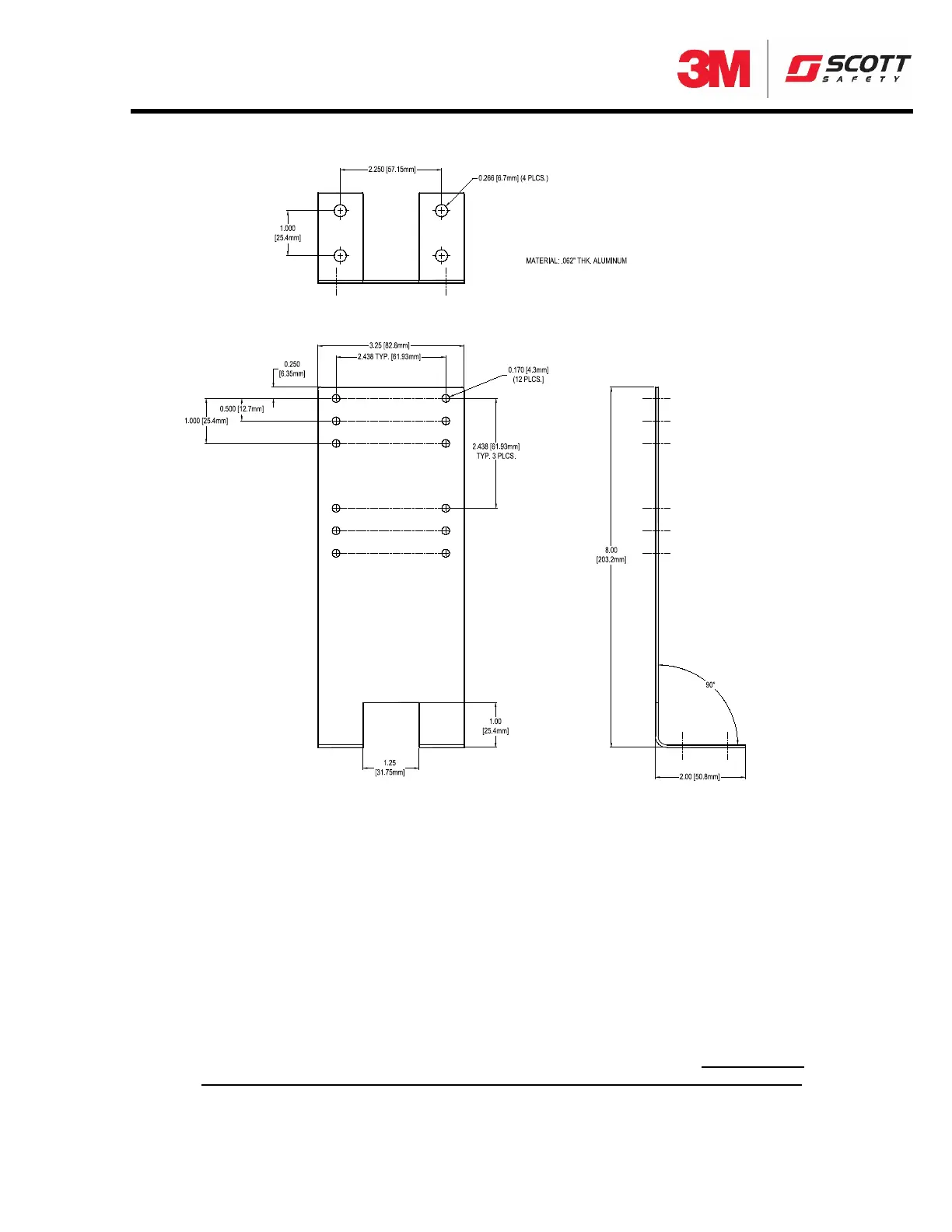
Figure 6 L Mounting Bracket
Installation i
s as follows:
STEP 1 - Make all phys
ical connections (i.e., conduits, pipes, enclosure, plastic spacer
block, junction box, etc.)
STEP 2 - Loosen transm
itter screws and pull down front panel lid.
STEP 3 - Make wire co
nnections (14 to 22 AWG wire) in accordance with Figure 7.
Note that the Freedom™ 5000 is a two wire (loop powered transmitter) and it is polarity
insensitive, thus making wiring extremely simple. Ensure that proper wire gauge is used
and that all wire, electrical grounds, and sensor connections are secure and intact.
STEP 4 - Close lid and tighten transmitter screws, ensuring a tight seal. It is important
to hold the lid down tight while tightening the screws and not allow the screws to
Freedom 5000 Universal Analog Toxic Gas Detector
Instruction Manual