Do you have a question about the 3M FREEDOM 5000 and is the answer not in the manual?
Provides important notices regarding the use and responsibility for the equipment.
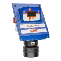
Provides a general overview of the Freedom 5000 toxic gas transmitter and its capabilities.
Explains the working principles of electrochemical gas sensors used in the Freedom 5000.
Details how sensors are designed for specific gases and potential interferents.
Discusses factors limiting accuracy and expected performance.
Covers how sensor response time is optimized and what affects it.
Provides guidance on expected sensor life and factors influencing it.
Details the minimum oxygen levels required for sensor operation.
Explains the intrinsically safe design and its implications for explosive atmospheres.
Provides instructions for safe handling and disposal of sensors.
Describes the transmitter's general purpose loop-powered operation and output.
Highlights unique circuitry, RFI immunity, LCD, and diagnostic alarms.
Explains the magnetic switches for control and identifies status indication flags.
Details the function of the four magnetic switches for setup and calibration.
Describes the modular design of the transmitter circuitry and its protective coating.
Key factors to consider when choosing a mounting location for the transmitter and sensor.
Guidance on vibration, accessibility, water, EM fields, air velocity, seals, and material compatibility.
Details the power consumption of the 4-20mA loop.
Describes the three typical ways to mount the transmitter enclosure.
Instructions for making all physical connections like conduits and enclosures.
Details on making wire connections, noting polarity insensitivity.
Steps for installing the sensor, including the elastomeric pad and alignment.
Shows how to wire the unit and use a multimeter for testing.
Describes options for integral cables for remote sensor placement.
Details options for using conduit and flexible fittings for remote sensors.
Warns about PVC compatibility and requires electrical isolation of sensor housing.
Details Rain Shields, Splashguards, and Calibration Adaptors.
Explains Remote and Direct Duct Mount Adaptors for duct installation.
Describes Flowcell options for sample draw configurations.
Outlines the steps for powering up the transmitter and initial checks.
Explains how the inhibit function prevents external alarms during calibration.
Details how to program the inhibit output level for the transmitter.
Guides on adjusting the inhibit loop current value via magnet input.
Provides minimum recommended intervals for zero and span calibration.
Offers tips for documenting schedules, organizing sensors, and storing spares.
Details the steps to remove and calibrate the sensor at a remote location.
Explains critical storage requirements for pre-calibrated sensors.
Explains setting the transmitter's zero by adjusting loop output to 4 mA.
Covers using ambient air or a permeation tube device for zeroing.
Details span gas concentration, expiration, and oxygen requirements.
Provides detailed steps for performing the span calibration process.
Guides on finalizing span calibration, checking factor, and exiting inhibit mode.
Details mandatory calibration methods for specific sensor types like HF.
Covers special requirements for hydride and ammonia sensors calibration.
Recommends weekly checks to ensure the sensor responds to the target gas.
Explains how fault codes and flags are displayed on the LCD.
Details the 'SEN' and 'SST' flags and their meanings.
Lists common fault codes (F01, F02, F04, F08) and their causes.
Explains the SST option for automatic sensor testing and its benefits.
Guides on how to activate and program the SST function using the magnet.
Describes the instrument's behavior and checks during the SST process.
Covers recommended zero and span adjustment intervals.
Details sensor membrane cleaning and pop-in replacement process.
Provides guidance on when and how to replace the elastomeric connector.
Steps to isolate problems to sensor, board, or connection failures.
Instructions for using a sensor simulator to diagnose transmitter issues.
Explains causes and detection of zero drift and false alarms.
Focuses on issues related to the elastomeric connector and connections.
Details fault codes displayed on the LCD and their corrective actions.
Describes how to reset sensor calibration values to factory defaults.
Recommendations for keeping spare circuit boards and general handling.
Step-by-step instructions for removing and replacing the CPU board.
Guides for removing and replacing the Power Supply - I/O board.
Instructions for removing and replacing the Display board.
Lists available spare parts for rain shields, end-caps, adaptors, and filters.
Lists spare parts specifically for remote sensor configurations.
Includes miscellaneous items like connectors, tools, and manuals.
Lists spare electronic boards including I/O, CPU, and Display boards.
Lists spare parts for enclosures, mounting brackets, and sensor fittings.
Guides on selecting the appropriate gas type and measurement range.
Details options for integral or separated sensor connections.
Covers adapter types and the SST option configuration.
Outlines the general warranty coverage for manufacturer's products.
Details the specific warranty period for gas sensors and exceptions.
Covers conditions for warranty claims, exclusions, and voiding factors.
Provides contact details for Scott Safety customer support.
Lists specifications for enclosure, repeatability, linearity, output, power, and display.
Details operating temperature, humidity, weight, routines, and approvals.
Details CSA/NRTL approval, electrical code, and entity conditions for barriers.
Illustrates the wiring connections for intrinsically safe barriers.
Provides wire color and pin assignments for integral and remote sensors.
| Gas Detected | Oxygen (O2), Carbon Monoxide (CO), Hydrogen Sulfide (H2S) |
|---|---|
| Operating Temperature Range | -4 to 122°F (-20 to 50°C) |
| Battery Life | 18 hours typical |
| Sensor Type | Electrochemical (O2, H2S, CO) |
| Alarms | 95 dB audible alarm, vibrating alarm |
| Certifications | ATEX, IECEx, UL |