45
087-0020 REV E
Zero and Span Calibration
Zero and Span Calibration
Zero and Span Calibration
Resetting Factory Default Calibration Values to Sensor
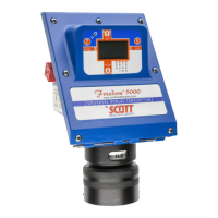
By applying a magnet simultaneously to the “Z” and “S” spots on the Freedom™ 5000 for 1-2
seconds you will reset the zero and calibration data stored inside the GasPlus sensor back to the
factory default levels. This feature is very useful if a very poor calibration was performed on a sensor
and you need to clear that data, e.g. “zero” an oxygen sensor with room air. Upon applying the two
magnets the display will show
“rSt”.
Circuit Boards
General
Depending on the tota
l number of Freedom™ 5000 instruments installed at your facility, it is
recommended that at least 1 of the following circuit boards be kept as spare parts.
1- Input/Output (I/O);
1- Power Supply (P.S.);
1- Display
Due to the complexity of the circuit boards it is advisable that all troubleshooting be accomplished by
interchanging boards with your spares.
Remove Boards
1. Loosen all t
he housing captive screws and open the hinged lid. The lid will open
downward. The Power Supply and Display board will now be exposed.
2. Remove the loop wires from terminals 1 and 2, and keep them insulated from any
metal object.
CPU Board Removal
To remove the C
PU board you first must remove the Power Supply - I/O board.
3. Unplug the ribbon cable from the Power Supply board then unplug the sensor
connector from the CPU board.
4. Remove the 3 screws holding the P.S. board in place and remove by pulling
up
ward. Note: The CPU board will now be exposed.
5. Unscrew the 3 hex standoffs and remove by tilting the board and pulling upward.
6. Replace board.
7. Follow steps in reverse (5 - 1) to complete the change out of the CPU board.
Caution: Be careful when re- connecting the ribbon and sensor cables that you do
not bend the connector pins.
Freedom 5000 Universal Analog Toxic Gas Detector
Instruction Manual