31
087-0020 REV E
Start – Up
Front Panel Operations and Indications
Initial System Start - Up
Once all transmitters (sensor, rain shield, etc.) have been assembled and installation
has been completed, the DC supply to the Freedom
™ 5000 Transmitter may be
energized.
Once power
is applied, the transmitter will initialize an LCD character display test
routine. Verify that all character segments are displayed. In addition, the transmitter will
detect and display sensor gas type (52=chlorine, 80=oxygen, etc.) and its full-scale
range. (Refer to the Operating Specifications in the Appendix Section for a complete list
of sensor gas type numbers). Once display information is completed, the Series 5000
Transmitter loop power is held at the user selected loop inhibit level (default 4 mA) for
approximately 30 seconds to permit sensor stabilization.
Alarm and Loop – Power Inhibit
The Freedom
™ 5000 Transmitter’s inhibit function prevents activation of external alarms
by holding the loop output at the selected inhibit output level (see below) during
calibration. To activate (or deactivate) the inhibit function, use the magnet and
momentarily place it over the “Z” (ZERO) calibration zone.
Observe the LCD indicates the “IHB” function is active. The inhibit mode can be
manually deselected by reapplying the magnet to the “Z” (ZERO) calibration zone.
Freedom
™ 5000 will automatically return to run mode approximately 10 minutes
after the last adjustment OR after 30 seconds upon reinstallation of a sensor.
Setting Inhibit Loop Current
The Freedom
™ 5000 transmitter inhibit output may be programmed to a value of 3.2 mA
to 20 mA. Inhibit outputs can be set in 0.1 mA increments.
To change the inhibit output proceed as follows:
1. Hold the magnet momentarily over the “Up” or “Down” spot until “Ihb” is displayed.
See figure 14. The display will first indicate “Ihb” or “SST” depending upon options
purchased.
2. Hold the magnet momentarily over the “S”- Enter switch.
The display will now indicate the current inhibit value in a flashing
mode.
Figure 14 Inhibit Mode
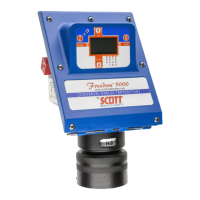
Freedom 5000 Universal Analog Toxic Gas Detector
Instruction Manual