26
087-0020 REV E
provide the force. This prevents the possibility of pulling the screw sockets out of
the housing.
STEP 5 – Install the sensor into the sensor housing. Make sure the elastomeric pad is
between the sensor and the sensor housing concentric rings. Match the alignment pin in
the sensor with the stainless steel pin in the sensor housing. The elastomeric pad can
be installed with either side facing up or down. Rotate the sensor until it locks into the
alignment pin. The gas name/range will be visible through the housing front. To ensure
proper connection between the sensor and housing, tighten the threaded sensor end
cap hand tight – do not over-tighten as this could damage the elastomeric connector or
the sensor housing!
Refer to Figures 8 & 9.
Figure 7 Wiring & Testing
TB1
1+ - 2
+ 24 V DC
4-20 mA INPUT
RECEIVER
SHIELD GROUND
AT RECEIVER ONLY
RIBBON CABLE TO
FRONT PANEL
+
_
mV
40.00
MULTI-METER SET
TO mV RANGE
TP1 TP2
-
- +
0
0
NOTE: TP1 AND TP2 ARE USED
TO MEASURE 40 TO 200 mV DC
CORRESPONDING TO THE
4 TO 20 mA OUTPUT SIGNAL
NOTE: ALTHOUGH TB1 IS MARKED AS
1 (+) AND 2 (-) THE SERIES 5000 TRANSMITTER
IS NOT POLARITY SENSITIVE
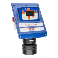
Freedom 5000 Universal Analog Toxic Gas Detector
Instruction Manual

 Loading...