44
087-0020 REV E
STEP 6 – Set the voltage calibrator to input 0.550 mV.
Using the magnetic tip of the screwdriver, touch the magnet to the “S” span
point on the transmitter body and hold it there. After four seconds the bar
graph will disappear and the reading will begin to flash. Adjust the UP or
Down buttons with the magnet until full scale (100ppm) is indicated. Hit the
“S” – Enter spot and the word “Set” will momentarily be shown.
Remove the magnet. The display should read full-scale (100ppm) and the
DVM should read 200 mV.
If sensor simulation indicates that the transmitter is functioning properly, the problem
does not reside with the transmitter electronics. Check the elastomeric pad, sensor, and
calibration source & or technique.
Zero Drift and False Alarms
If “zero drift” (unexplained output when the target gas is not present) is noted, the
problem could be the presence of an interferent gas. This is particularly true if the sensor
is a low range oxidant gas type (e.g., chlorine, ozone, etc.) in the low PPM full scale
range. It is not uncommon for background atmospheric ozone, for example, to be
present on sunny days in concentration ranges of up to and exceeding 140 PPB.
If you notice a regular increase in output on dry, sunny afternoons you should contact
your clean air monitoring office to see if high ozone levels are present. When trying to
detect gases at less than 1 PPM (1000 PPB) concentration levels, many interferences
may be present – particularly if close to an active industrial environment.
Poor Electrical Connection
Possible Problem – Elastomeric Connector
Good electrical connection between the sensor and the transmitter is dependent upon
the elastomeric connector. If both the original sensor and the simulator produce an
intermittent output or no output at all, the problem may be the elastomeric connector.
Test to ensure that the threaded end cap is not loose. Also, the connector may have
become damaged due to ingress of dirt or exposure to a corrosive atmosphere.
In these cases replace the elastomeric connector.
Fault Codes and Error Messages
When the transmitter detects a fault, the error code F0# appears on the display.
The current loop output will go to the programmed fault level (3.1 mA ), unless the
transmitter is in inhibit mode (also visible on the display).
FAULT CODE
DISPLAY
MESSAGE POSSIBLE CORRECTIVE ACTION
F01 Loop Cal Failure Recheck Accuracy Of Calibration Gas
Replace Sensor & Or Elastomeric Pad
F02 SST Failure
(Sensor Self Test )
Verify the SST is operating properly
Verify wind speed is less than 22 MPH
Replace Sensor & Or Elastomeric Pad
F04 Future Use
F08 Missing Sensor
Indicator
Re-seat Sensor
Tighten Down On End Cap
Replace Elastomeric Pad
Required Procedure After Replacing Equipment
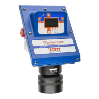
Freedom 5000 Universal Analog Toxic Gas Detector
Instruction Manual