46
087-0020 REV E
8. Set-up and calibration must now be carried out to complete the board change.
Power Supply – I/O Board Removal
Follow steps 1 through 4 listed under the CPU board removal.
5. Replace board.
6. Follow steps in reverse (4 – 1) listed under the I/O board removal to complete the
change out of the P.S. board.
Caution: Be careful when re-connecting the ribbon and sensor cables that you do
not bend the connector pins.
7. Set-up and calibration must now be carried out to complete the board change.
Display Board
Follow steps 1 through 2 listed above.
3. Un-plug the ribbon cable from the Display board, remove the 2 screws and life the
board from the 2 positioning pins.
4. Replace board.
5. Follow steps in reverse (3 - 1) to complete the change out.
Caution: Be careful when re- connecting the ribbon cables makes sure that you
do not bend the connector pins and the board fits over the 2 alignment pins.
6. Set-up and calibration must now be carried out to complete the board change.
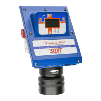
Freedom 5000 Universal Analog Toxic Gas Detector
Instruction Manual