36
087-0020 REV E
The transmitter should begin to respond to the calibration gas within 30
seconds. The indicated gas concentration should slowly level off to a value
(usually close to that of the span gas concentration) and remain stable. Once
this value has reached equilibrium it is time to span the transmitter/sensor.
STEP 5- Using the magnet, place the magnetic tip over the ’’S’’ (SPAN) - Enter spot on
the transmitter body and hold it there. After four seconds the reading will begin
to flash, the bar graph and the inhibit indicator flags (if activated) will disappear.
Note: If the unit was inhibited prior to beginning the span calibration it will
remain activated. Touch the magnet to either the “” UP or “” Down spot to
increase or decrease the concentration displayed.
Once the displayed concentration has reached the desired reading, touch the
magnet to the ’’S’’- Enter spot. The Transmitter will then momentarily display
the word “Set” followed by displaying the calibration factor. The calibration
factor has an inverse relationship to the amount of gain applied to derive the
correct 4-20 mA output signal. This value ranges from 120 – 1780. Sensors
that show a calibration factor of 250 or less are approaching the end of
their useful life and should be replaced soon. When the calibration factor
reaches 150, the transmitter will display the “SEN” flag to indicate that
the sensor requires replacement. The "SEN" flag will remain until the
sensor is replaced.
After displaying the cal factor the Freedom
™ 5000 will automatically return to
displaying the present gas concentration.
STEP 6 –Remove the calibration gas from transmitter. Once the display is below the
alarm level take the transmitter out of inhibit mode by momentarily applying
the magnet to the “Z” (ZERO) point.
Observe that the (2) inhibit indication flags are no longer visible.
NOTE: If the transmitter is not manually taken out of inhibit mode it will
automatically return to run mode about 9 minutes after the last
adjustment. After calibration is complete, disconnect the calibration system.
The unit should now be operating properly and displaying the current gas
concentration. Some sensors may require several minutes to return to a true
zero value. Do not re-zero the unit at this time.
Mandatory Calibration Method of HF & Rock Solid Acid* Gas
Sensors
*Includes: HF – HCL – HBr – SO2 – WF6 – SiF4 – BF3 – BCL3
Scott Safety has traditionally informed customers to use chlorine as a cross-calibration
gas for hydrogen fluoride (HF) sensors. This was due to the difficulty in getting accurate
low levels of HF in a cylinder or generator.
Permeation tubes, which can provide a low-level accurate source of HF,
were found to be difficult to use. Recently it has been learned that the HF
sensor can, after some aging, lose its ability to detect HF while maintaining its ability to
sense chlorine.
The potential danger is that a conventional HF sensor or Rock Solid Acid gas sensor
deemed to be working properly is in fact insensitive to HF or acid. The reason for this
If the calibration
factor is below 150
a flag indicator will
be displayed
above the “SEN”
on the front
display.
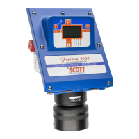
Freedom 5000 Universal Analog Toxic Gas Detector
Instruction Manual
 Loading...