4
087-0020 REV E
List of Figures
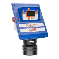
Figure 1. Freedom 5000 with Integral Sensor ................................................................. 15
Figure 2 Sensor Operation .............................................................................................. 16
Figure 3 Interface ............................................................................................................ 20
Figure 4 Inside View ........................................................................................................ 22
Figure 5 Dimensional Drawing (with optional wall mount bracket) .................................. 23
Figure 6 L Mounting Bracket ........................................................................................... 25
Figure 7 Wiring & Testing ................................................................................................ 26
Figure 8 Installation of E-Pad, GasPlus Sensor and Endcap .......................................... 27
Figure 9 E-Pad Separate & Installed in Endcap .............................................................. 28
Figure 10 Remote Sensor and Flat Duct Mount .............................................................. 29
Figure 11 Calibration Adaptor ......................................................................................... 30
Figure 12 Remote Duct Adaptor ...................................................................................... 30
Figure 13 Direct Duct Mount Adaptor .............................................................................. 30
Figure 14 Inhibit Mode ..................................................................................................... 31
Figure 15 Setting Inhibit .................................................................................................. 32
Figure 16 Zero Calibration ............................................................................................... 34
Figure 17 With SST Option ............................................................................................. 39
Figure 18 Sensor Self Test Generator ............................................................................. 40
Figure 19 E-Pad & Sensor .............................................................................................. 41
Figure 20 096-2002 ......................................................................................................... 43
Figure 21 Supply Voltage – CD ....................................................................................... 57
Figure 22 I. S. Barrier Wiring Diagram ............................................................................ 60
Freedom 5000 Universal Analog Toxic Gas Detector
Instruction Manual