Quick Installation Guide
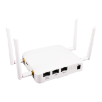
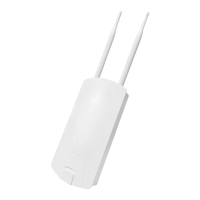
EAP706 Enterprise Access Point ENGLISH
Copyright © 4IPNET, INC. All rights reserved.
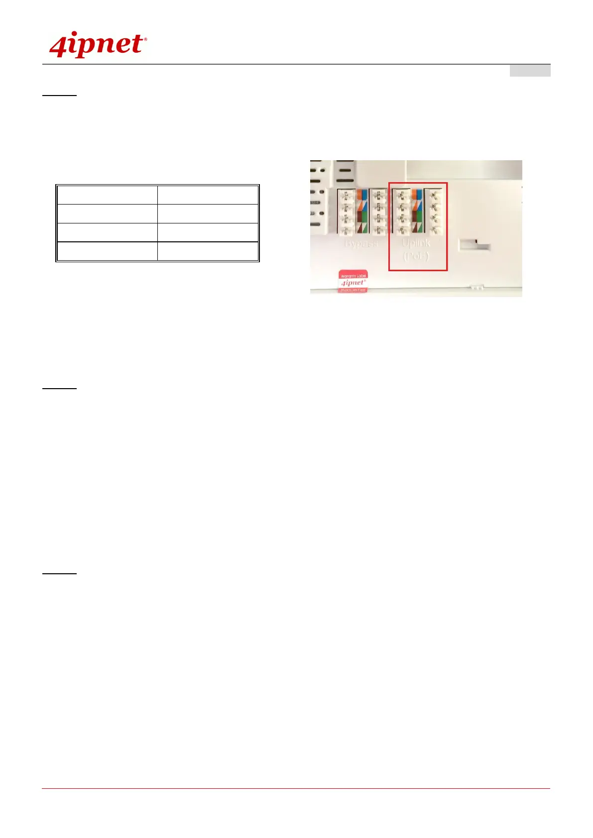
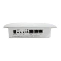
Step 2. Connect one end of the Ethernet cable to the Uplink port and the other end of the cable to a switch,
a router, or a hub; or use the 110 punchdown block as your uplink connection. The 110 punchdown
block may be connected with the following pin assignment:
The EAP706 is now connected to your existing wired LAN network.
Step 3. There are three ways to supply power to EAP706
a) Connect the DC power adaptor to the power jack socket.
b) The Uplink port is capable of receiving PoE. Connect an IEEE 802.3af-compliant PSE device
(e.g. a PoE-switch) to the Uplink port of EAP706 with the Ethernet cable.
c) Use a standard 110 punchdown tool to punch copper wires onto the punchdown block (uplink)
Step 4. Fasten the Access Point to the mounting plate
a) Align the Access Point to the mounting plate using the arrow printed on the back of the Access
Point.