Page 08
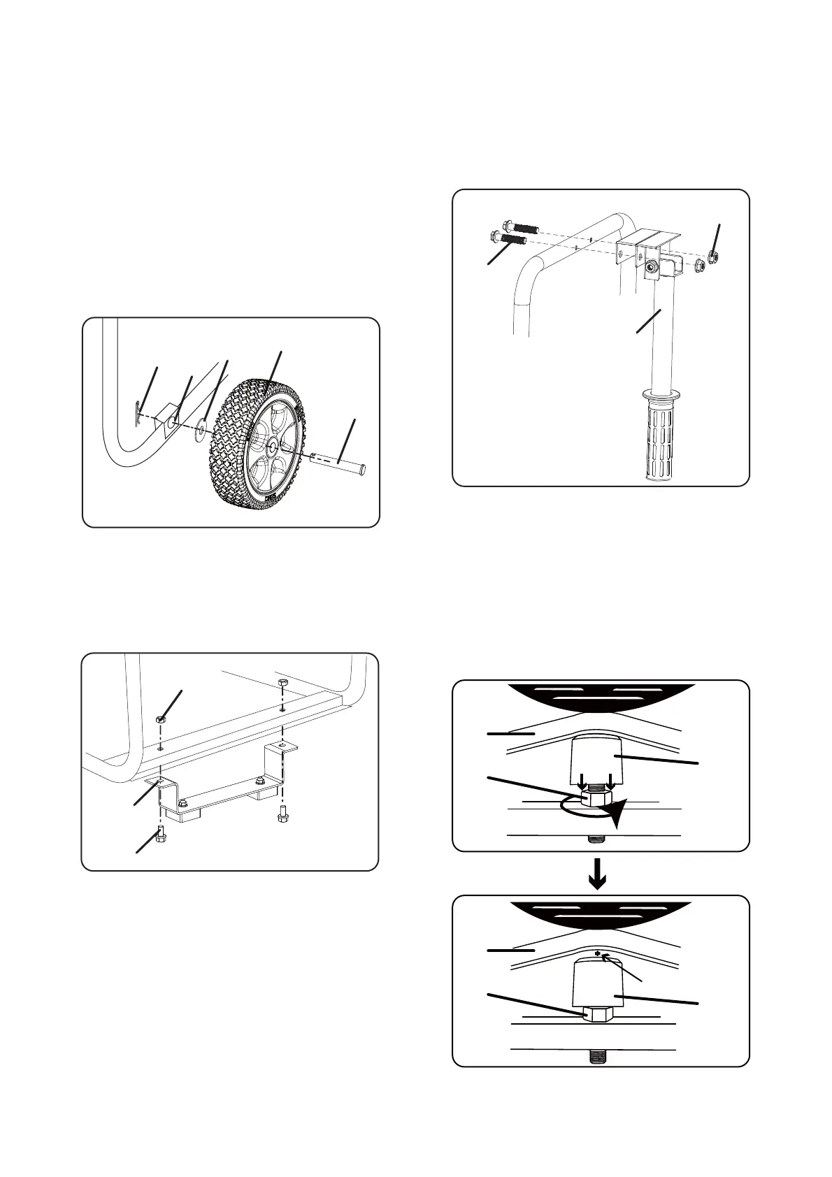
Install the Wheel Kit
NOTE:
The wheels are not intended for over-the-road use.
IMPORTANT: Before operating the generator the
shock-absorbing seat (N) must be adjusted for
clearance. Loosen the lock nut (L) and adjust the
shock absorbing seat (N) so there is about 3-4mm
gap between the top of the seat and the bottpm of
the alternator bracket (M). Re-tighten the lock nut
after adjustment.
3-4mm
1 - place generator on a flat surface.
2 - Tip the generator on a piece of cardboard or
other soft material to protect the frame paint and
prevent the generator from sliding.
3 - Slide axle pin (A) through the wheel (B), flat
washer (C) and generator frame axles hole (D).
4 - Secure everything with cotter pin (E). Repeat on
opposite side.
M
N
L
M
N
L
A
B
C
D
E
Install the Support Leg
5 - Insert bolts (F) throught the support leg (G) and
holes on the generator frame as shown.
6 - Tighten bolts (F) and nuts (H) to the frame.
Install the Handle Assy
7 - Unscrew bolts (I) and nuts (K) on the handle.
8 - Insert bolts (I) throught the handle (J) and
holes on the generator frame as shown.
9 - Tighten bolts (I) and nuts (K).
G
F
H
I
J
K