Instruction manual - BMS Interface
4. For Cyclone BFC systems, the communication cable
must be connected to the BUS link connections (X5 and
X6) on the far right side of the electrical connection box
on top of the water heater.
It is possible to select another, longer communication
cable for communication between the BMS Interface
and the water heater or solar control. The cable
diameter is free to choose. However, the maximum
length of the cable depends on the cable diameter, see
the table.
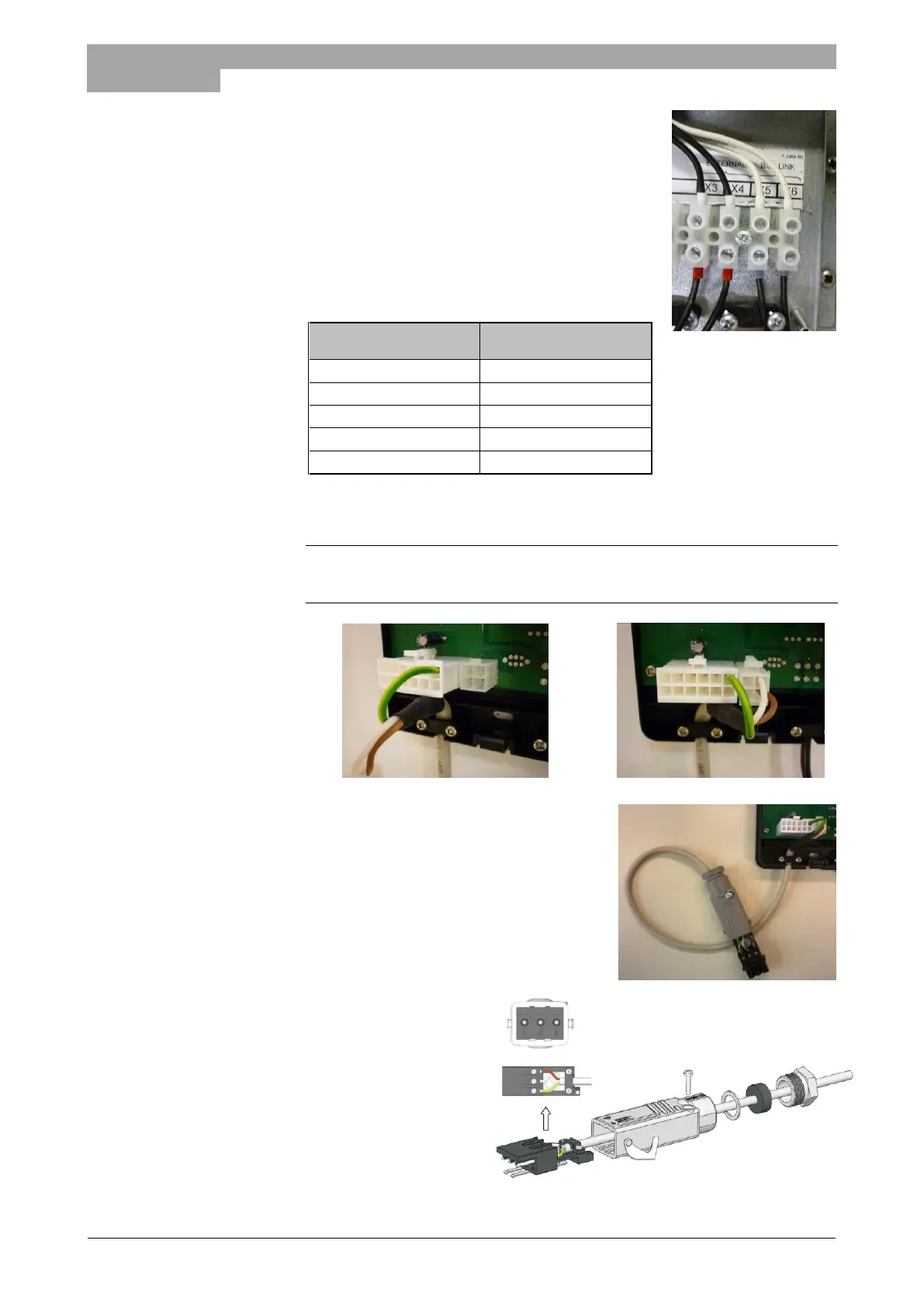
5. Connect the communication cable for Modbus connection, via the pull relief, to the
two connectors on the lower side of the BMS Interface.
ATTENTION:
First connect the twelve way connector containing the ground wire, next the four way
connector can be connected.
6. Afterwards connect the Modbus communication
cable to the building management system in the
required way. For this purpose use the
connectors which are supplied together with the
BMS Interface.
7. Connect the cable from the
building management
system to the supplied
contra connector. First
lead the cable through the
pull relief. This three wire
cable (2 wires + PE) is not
supplied with the BMS
Interface. Make sure that
the wires are connected in
the right sequence.
1 = brown Modbus 1 - Tx+
2 = white Modbus 1 - Tx-
3 = yellow/green Earth