Do you have a question about the A.O. Smith Water Heater 520 Direct Vent Indoor and is the answer not in the manual?
| Brand | A.O. Smith |
|---|---|
| Model | 520 Direct Vent Indoor |
| Category | Water Heater |
| Type | Direct Vent |
| Fuel Type | Natural Gas or Propane |
| Tank Capacity | 50 gallons |
| First Hour Rating | 90 gallons |
| Venting | Direct Vent |
| Warranty | 6 years |
Details on burner function, failure events, and diagnostic information.
Information on gas distribution, zones, and failure events.
Describes fan motor function, failure events, and electrical specifications.
Details exhaust fan motor function, failure events, and diagnostic checks.
Explains gas valve functions, failure events, and diagnostic checks.
Describes flame detection function and failure modes.
Explains AFR rod function in checking flame conditions and error codes.
Details heat exchanger function, failure events, and diagnostic criteria.
Describes secondary heat exchanger function and failure events.
Explains flow sensor function, failure events, and diagnostic checks.
Details water control valve functions, failure events, and diagnostic checks.
Describes thermistor function and failure conditions.
Details exhaust thermistor function and failure conditions.
Explains hi-limit switch function and failure consequences.
Describes hi-limit switch for exhaust function and failure.
Details overheat cutoff fuse function and failure effects.
Explains freeze protection heater function and failure effects.
Describes computer board function and failure consequences.
Explains transformer function and failure effects.
Details igniter function and failure consequences.
Explains freeze protection thermostat function and failure effects.
Describes surge box function and failure effects.
Method for checking information via computer board diagnostic mode.
Method for checking information via remote controller diagnostic mode.
Verifying board operation, displaying, and clearing error history.
Procedure for clearing specific error codes after root cause resolution.
Explains AFR rod function and its relation to combustion and error codes.
Details the functions of the right and left dipswitch banks.
Procedures for displaying and reconfiguring unit numbers in a system.
Shows general ON/OFF conditions for the water heater operation.
Calculation of ON/OFF conditions based on BTU requirements.
Describes pump control modes and their ON/OFF conditions.
Calculation of pump ON/OFF conditions based on BTU requirements.
Conditions for activating/reducing units in an Easy-Link system.
Explains how primary unit rotation occurs based on cycles or hours.
How units operate individually when the parent unit fails.
Explains altitude support functions via dipswitch settings.
Method to change temperature display unit (Celsius/Fahrenheit).
Explains exhaust temperature control mechanisms for the 520 Indoor model.
Guidelines for selecting appropriate relays for pump control connections.
Function of the alarm port for notifying users of error codes.
Procedures for adjusting maximum and minimum manifold gas pressure.
Procedures for manual fan motor speed adjustment using a remote controller.
Describes the automatic firing system and ceramic heating blocks for freeze protection.
Explains freeze protection for recirculation pumps in an Easy-Link system.
Step-by-step guide for safely draining the unit and cleaning the water filter.
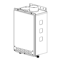
Exploded view of the unit's case assembly.
Diagram showing components of the computer board.
Diagram illustrating the burner assembly.
Diagram of the water way components and connections.