Zone
Zone
Two Condenser Head Pressure II Module Technical Guide
15
TROUBLESHOOTING
Pressure Transducer Troubleshooting and LEDs
Table 7: Two Condenser Head Pressure II Module
Transducer Chart
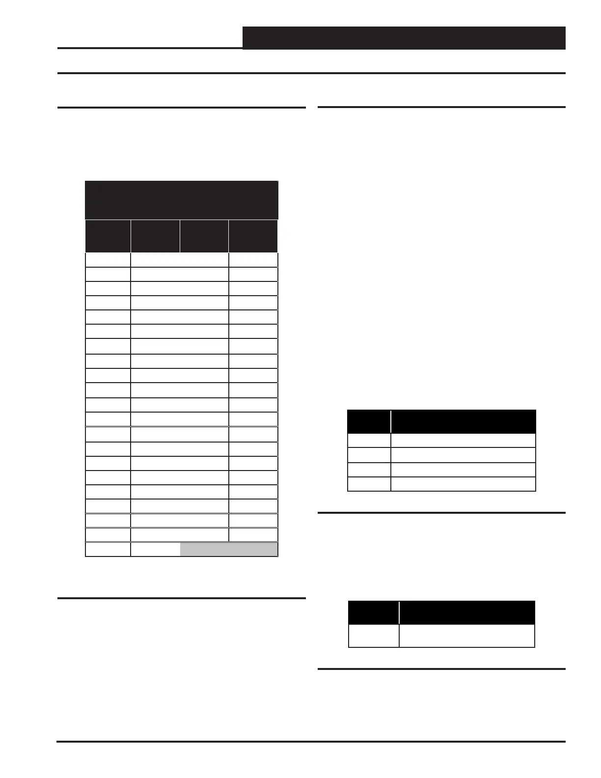
Pressure Transducer Troubleshooting
If you suspect there is a problem with the Module related to
pressure transducer measurements, reference Table 7 below.
Pressure Sensor Chart
Voltage Pressure Voltage Pressure
0.5 0 2.6 350
0.6 17 2.7 367
0.7 33 2.8 384
0.8 50 2.9 400
0.9 67 3.0 417
1.0 83 3.1 434
1.1 100 3.2 450
1.2 117 3.3 467
1.3 133 3.4 484
1.4 150 3.5 500
1.5 167 3.6 517
1.6 183 3.7 534
1.7 200 3.8 550
1.8 217 3.9 567
1.9 233 4.0 584
2.0 250 4.1 600
2.1 267 4.2 617
2.2 283 4.3 634
2.3 300 4.4 650
2.4 317 4.5 667
2.5 334
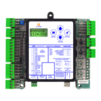
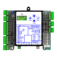
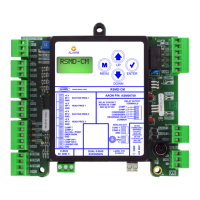
Using LEDs to Verify Operation
The Two Condenser Head Pressure II Module is equipped
with LEDs that can be used to verify operation and perform
troubleshooting. There are LEDs for communication, operation
modes, diagnostic codes, and relays. The Two Condenser Head
Pressure Module has eight LEDs—one for power, one for
operation status, one for communication, one for alarms, and
four for compressor relays. See Figure 6 for the LED locations.
The LEDs associated with these inputs and outputs allow you to
see what is active without using a voltmeter.
Status LEDs
“COMM” - This LED will light up to indicate Communications
with the VCM-X series or SA series controller. If Communications
are established, the COMM LED will blink. You should not see
this LED light up in stand-alone mode, because there would be no
communications with the VCM-X series or SA series controller.
“ALARM” - This is the diagnostic blink code LED. It will light up
and blink out diagnostic codes. See Table 8 below for Diagnostic
Blink Code descriptions. The blink code descriptions are also
located on the Module’s front cover.
No. of
Blinks
Alarm
0
No Problems
1
No Sensors Detected
2
High Head Pressure Detected
3
Low Head Pressure Detected
Table 8: ALARM LED Blink Codes
“STAT” - This is the status blink code LED. It will light up and
rst blink the address of the Module. It will then blink out the
quantity of sensors installed. See Table 9 below for Status Blink
Code descriptions. The blink code descriptions are also located
on the Module’s front cover.
No. of
Blinks
Status
Random
Blinks Quantity of Sensors
Installed
Table 9: STAT LED Blink Codes