Do you have a question about the AAON RSMD-CM and is the answer not in the manual?
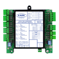
Describes the capabilities and intended use of the RSMD-CM module.
Provides physical dimensions and specifications of the RSMD-CM module.
Details electrical specifications and environmental operating conditions for the module.
Details the wiring connections for input signals to the RSMD-CM module.
Explains how to wire suction pressure transducers for accurate readings.
Details the wiring connections for output signals from the RSMD-CM module.
Explains how head pressure is controlled using the RSMD-CM module.
Discusses the function of compressor discharge temperature sensors.
Describes the use of the leaving water temperature sensor.
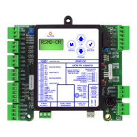
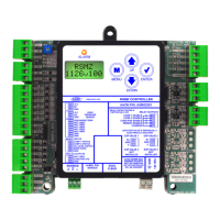
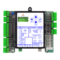
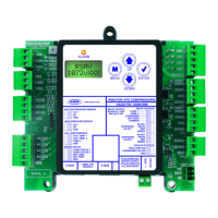
Provides a map of all input and output terminals on the RSMD-CM module.
Explains the 5 VDC power output for pressure transducers.
Details the function and application of suction pressure transducers.
Details the function and application of head pressure transducers.
Describes the inputs for compressor discharge temperature sensors.
Details the input for the leaving water temperature sensor.
Explains the function of compressor status binary inputs.
Details the use of the outdoor coil temp/proof of water flow input.
Explains the function of the emergency shutdown binary input.
Describes the 0-10 VDC output for condenser fan/valve control.
Details the output for bypass valve control.
Describes the relays for enabling compressors.
Describes the relays for enabling condenser fans/valves.
Describes the relay for enabling the reversing valve.
Explains cooling, dehumidification, and head pressure control sequences.
Details the compressor staging and modulation during cooling.
Describes operation with mixed compressor types.
Describes operation with multiple digital compressors.
Explains the process of staging compressors down.
Details the operation during dehumidification mode.
Explains head pressure control logic and setpoints.
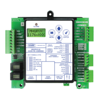
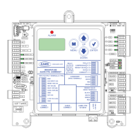
Describes the LCD display and the function of navigation buttons.
Provides a map for navigating through the main LCD screens.
Details the screens related to module configuration and status.
Describes the screens displaying current system operating status.
Details the screens showing readings from various sensors.
Describes the screens displaying current setpoint values.
Explains how to view and interpret alarms on the LCD display.
Continues the list and details of system alarms and fault conditions.
Details screens for viewing alarm history and accessing protected settings.
Explains how to access and modify configuration settings.
Describes the screens used for system diagnostics and status checks.
Details diagnostic screens for checking component status and modes.
Explains how to view alarm counts and configure module addresses.
Explains the function of diagnostic LEDs for verification and troubleshooting.
Provides steps and charts for testing suction pressure transducers.
Details testing procedures for discharge thermistor temperature sensors.
Provides tables for checking sensor voltage and resistance values.
Gives instructions for testing thermistor sensors using voltage and resistance.
Explains how to test the head pressure transducer.
Details wiring and configuration for two condensers per module.
Shows Prism 2 configuration for two condenser operation.
Lists HVAC units compatible with the two condenser configuration.
Details wiring for a single condenser per module setup.
Shows Prism 2 configuration for single condenser operation.
Lists HVAC units for single condenser per module configuration.
Details wiring for a single condenser across two modules.
Shows Prism 2 configuration for single condenser across two modules.
Lists HVAC units for single condenser per two modules configuration.
Details wiring for a single condenser across three modules.
Shows Prism 2 configuration for single condenser across three modules.
Lists HVAC units for single condenser per three modules configuration.
Details wiring for A1/B1 and A2/B2 condenser configurations.
Shows Prism 2 configuration for A1/B1 and A2/B2 condensers.
Lists HVAC units for A1/B1 and A2/B2 condenser configuration.
Details configuration for ON/OFF condenser operation.
| Input Voltage | 24 VAC |
|---|---|
| Power Consumption | 5 VA |
| Communication Protocol | BACnet MS/TP |
| Enclosure Rating | NEMA 1 |
| Operating Temperature | -40° to 158°F (-40° to 70°C) |
| Humidity Range | 95% RH, non-condensing |