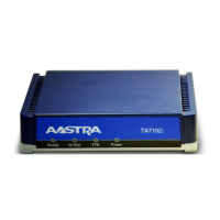
TA7102i Hardware Installation
© 2014 Aastra Sweden | 153_1531 ANF 90114| A | 2014-01-24 39
Table 10: RJ-45 Pinout Information
Pin #
Function
EIA/TIA 568A
Transmit -
Green with white stripe or solid
green
Orange with white stripe or solid
orange
N/A
Blue with white stripe or solid
blue
Blue with white stripe or solid
blue
Receive -
Orange with white stripe or solid
orange
Green with white stripe or solid
green
N/A
White with brown stripe or solid
brown
White with brown stripe or solid
brown
N/A
Brown with white stripe or solid
brown
Brown with white stripe or solid
brown
The RJ-45 cable uses two pairs of wires: one pair for transmission and the second pair for
reception. It is wired so that pins 1 & 2 are on one twisted pair and pins 3 & 6 are on a second
pair according to common wiring standards which meet the EIA/TIA T568A and T568B
requirements.
Figure 7: Straight Through Connectivity
Pin 1 Pin 1
Pin 2 Pin 2
Pin 3 Pin 3
Pin 6 Pin 6
Pin Name and Function
The following is the function of each pin in a RJ-45 cable.

 Loading...