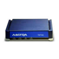
TA7102i Hardware Installation
© 2014 Aastra Sweden | 153_1531 ANF 90114| A | 2014-01-24 20
3.6 Hardware Installation
This section describes how to set the connectors of the TA7102i.
Warning: Do not connect the TA7102i directly to Telecommunication Systems.
Caution: The TA7102i must be installed on a circuit equipped with a breaker so that you can
easily power the unit off if required.
See Appendix B - Cabling Considerations, for more details on the cables the TA7102i uses.
Connecting Cables
The following describes how to connect the various cables to the TA7102i.
Figure 5: TA7102i Hardware Installation
2 4 3 5
1. Before you begin, be sure that the TA7102i is powered off.
2. Connect analog telephones or fax machines into the Pohne-Fax 1 and Phone-Fax 2
connectors. Use a standard telecommunication cord with a minimum of 26 AWG wire size.
Note: The TA7102i telephone line interface has been designed to interface with a conventional
telephone or fax machine. Connections to FXS ports of third party devices such as a PBX / Key
System could damage the TA7102i.
Connect a 10/100 BaseT Ethernet RJ-45 cable into the WAN connector of the TA7102i; connect
the other end to a compatible Ethernet interface that supplies TCP/IP network access (e.g.,
router, switch, hub or computer). Use a standard telecommunication cord with a minimum of 26
AWG wire size. You can either use a crossover or straight Ethernet cable because it performs
automatic MDI / MDIX detection. See “RJ-45 Cable”
for more details.
Connect a 10/100 BaseT Ethernet RJ-45 cable into the LAN connector of the TA7102i and
connect the other end to the network card of a computer. Use a standard telecommunication
cord with a minimum of 26 AWG wire size. You can either use a crossover or straight Ethernet
cable because it performs automatic MDI / MDIX detection. See RJ-45 Cable for more details.

 Loading...