• 2 - Remove the four screws which hold the CCD cover onto the
battery side of the camera and carefully remove the CCD cover.
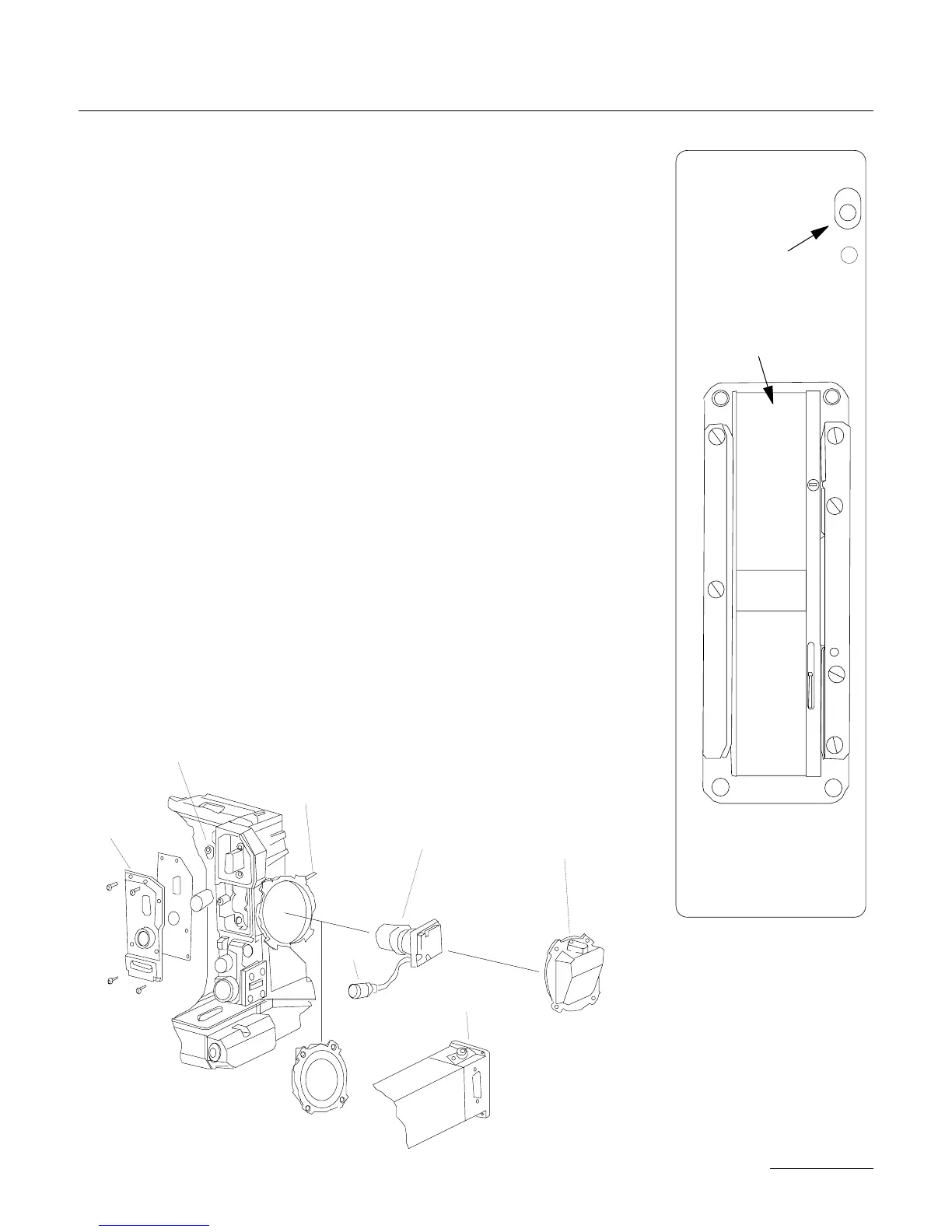
• 3 - Check that the exposed lens of the CCD head assembly is free
of dust particles. If necessary, clean this surface with lens fluid ap-
plied with a foam or cotton Q-tip. In order to install the head as-
sembly into the side cavity, first feed the Lemo14 connector into the
PBX so that it faces towards the rear of the camera. With the iris
rod facing up, install the head assembly into the tubular holder until
the steel collar is stopped by the tube.
• 4 - While holding the head assembly in place, locate the allen set
screw in the diagram above and tighten moderately until the head
assembly is secure. To avoid any damage to the relay lens housing,
do not overtighten this screw.
• 5 - Position the Lemo14 in its cutout within the PBX and hold in
place. Make sure that the flat index towards the rear of the connec-
tor faces up and mates with the flat in the cutout. Do not confuse
49
THE CAMERA BODY
Vis de réglage de la
lame vidéo
Canal film
Vis de réglage
de la lame vidéo
Vis Allen
fixant la cible CCD
Cible CCD
Cache cible CCD
Cotê plat
Visée vidéo
Plaque d’accueil
de la visée vidéo