bdiGDB for BDI2000 (PowerPC 7440/7450/86xx) User Manual 6
© Copyright 1997-2015 by ABATRON AG Switzerland V 1.13
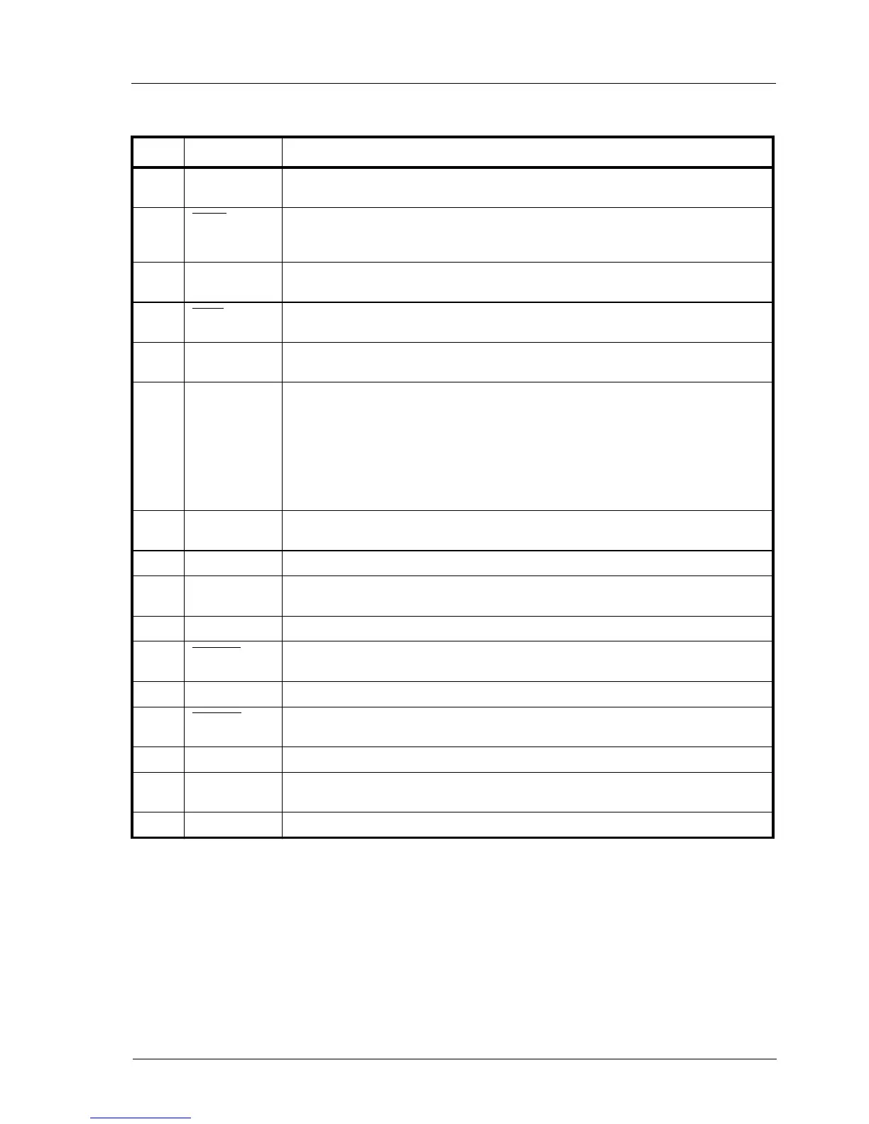
BDI TARGET B Connector Signals:
Pin Name Describtion
1 TDO JTAG Test Data Out
This input to the BDI2000 connects to the target TDO pin.
2
QACK QACK
This output of the BDI2000 connects to the target QACK pin. By default this pin is not driven
by the BDI2000. With an entry in the configuration file it can be forced low.
3 TDI JTAG Test Data In
This output of the BDI2000 connects to the target TDI pin.
4
TRST JTAG Test Reset
This output of the BDI2000 resets the JTAG TAP controller on the target.
5 IN0 General purpose Input
This input to the BDI2000 connects to the target HALTED pin. Currently not used.
6 Vcc Target 1.8 – 5.0V:
This is the target reference voltage. It indicates that the target has power and it is also used
to create the logic-level reference for the input comparators. It also controls the output logic
levels to the target. It is normally fed from Vdd I/O on the target board.
3.0 – 5.0V with Rev. B :
This input to the BDI2000 is used to detect if the target is powered up. If there is a current
limiting resistor between this pin and the target Vdd, it should be 100 Ohm or less.
7 TCK JTAG Test Clock
This output of the BDI2000 connects to the target TCK pin.
8 <reseved>
9 TMS JTAG Test Mode Select
This output of the BDI2000 connects to the target TMS line.
10 <reseved>
11
SRESET Soft-Reset
This open collector output of the BDI2000 connects to the target SRESET pin.
12 GROUND System Ground
13
HRESET Hard-Reset
This open collector output of the BDI2000 connects to the target HRESET pin.
14 <reseved>
15 IN1 General purpose Input
This input to the BDI2000 connects to the target CKSTP_OUT pin. Currently not used.
16 GROUND System Ground