bdiGDB for BDI2000 (PowerPC 7440/7450/86xx) User Manual 5
© Copyright 1997-2015 by ABATRON AG Switzerland V 1.13
2 Installation
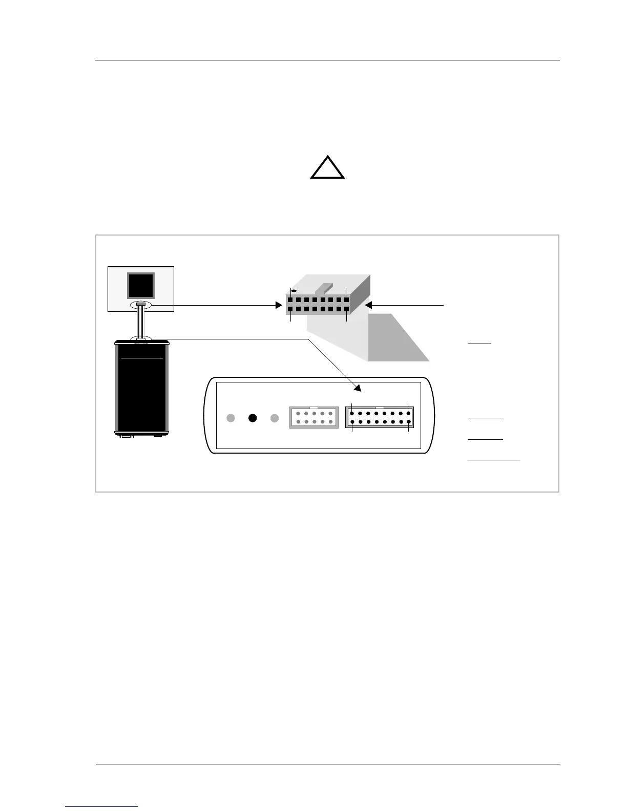
2.1 Connecting the BDI2000 to Target
The cable to the target system is a 16 pin flat ribbon cable. In case where the target system has an
appropriate connector, the cable can be directly connected. The pin assignment is in accordance with
the PowerPC COP connector specification.
In order to ensure reliable operation of the BDI (EMC, runtimes, etc.) the target cable length must not
exceed 20 cm (8").
For BDI TARGET B connector signals see table on next page.
!
COP/JTAG Connector
BDI2000
Target System
PPC
1
15
16
2
The green LED «TRGT» marked light up when target is powered up
BDI TRGT MODE TARGET A TARGET B
15 1
16
2
1 - TDO
2 - QACK
3 - TDI
4 -
TRST
5 - HALTED
6 - Vcc Target
7 - TCK
8 - NC (RXD)
9 - TMS
10 - NC (TXD)
11 -
SRESET
12 - GROUND
13 -
HRESET
14 - NC (key)
15 -
CKSTP_OUT
16 - GROUND