Chapter 2 – Overview of ACH 400 with Electronic Bypass
ACH 400 with Electronic Bypass User’s Manual 2-5
Detailed Description
of Operation
The following paragraphs provide a detailed description of the various
features and functions of the Electronic Bypass. Circuit diagrams for this
product are shipped with the unit.
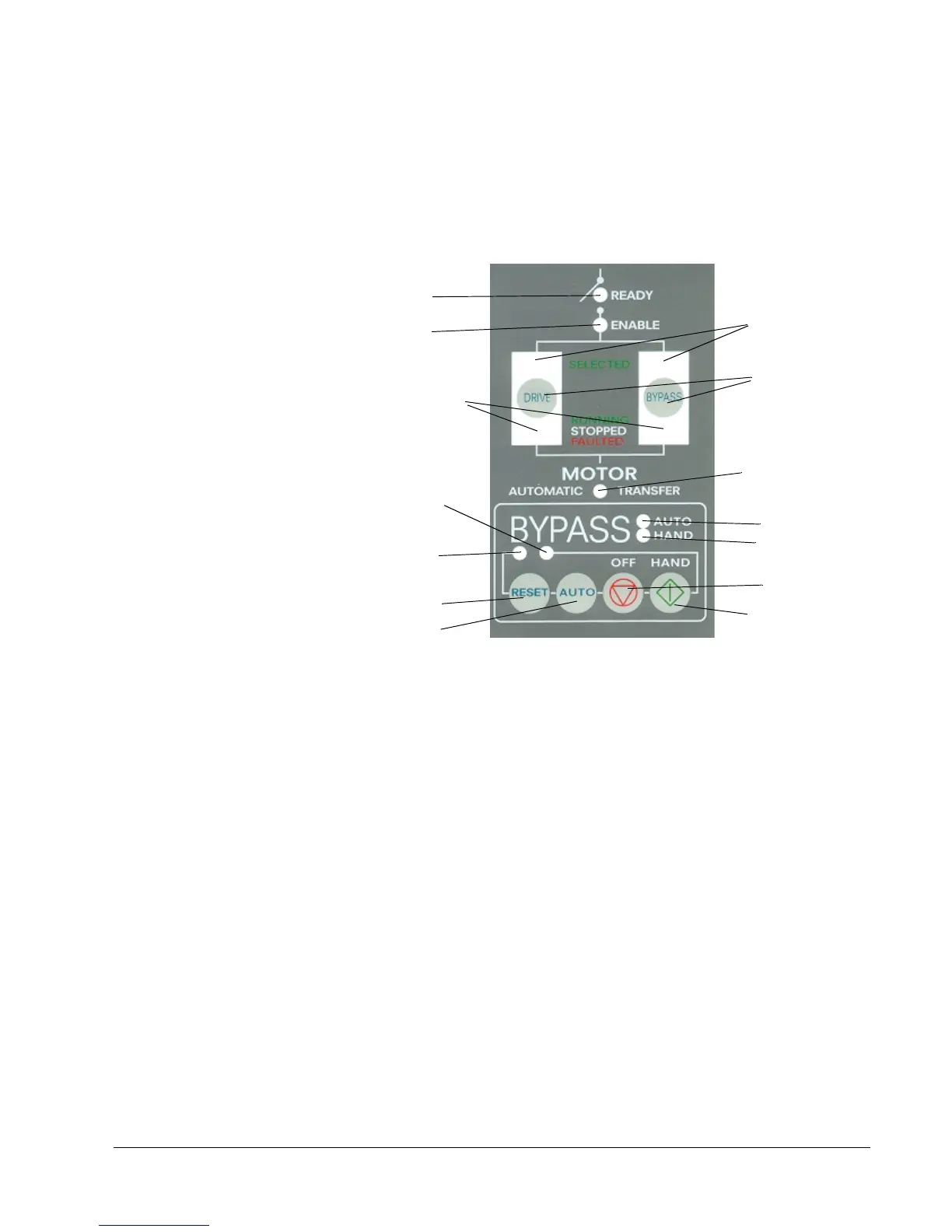
Bypass Control Keypad Figure 2-3 shows the bypass control keypad and identifies the keys and LED
indicating lights. The functions of the various keys and LEDs are described in
the following paragraphs.
Figure 2-3 Bypass Control Keypad
Ready LED The Ready LED is illuminated when the disconnect switch or circuit breaker
is closed and power is applied to the ACH 400 and bypass.
Enable LED The Enable LED is illuminated when the external enable interlock contacts
are closed.
Bypass Fault LED The Bypass Fault LED indicates the status of the bypass overload protection.
The LED is red when the overload has tripped or the bypass control board has
faulted.
Drive Run LED The Drive Run LED is illuminated green when the ACH 400 drive is running.
Drive Fault LED The Drive Fault LED is illuminated red when the motor or drive protection
functions have shut down the ACH 400.
Drive Selected LED The Drive Selected LED is illuminated green when the ACH 400 drive has
been selected as the power source for the motor.
Bypass Selected LED The Bypass Selected LED is illuminated green when the Electronic Bypass
has been selected as the power source for the motor.
Bypass Run LED The Bypass Run LED is illuminated green when the motor is running in
bypass.
Ready LED
Enable LED
Hand LED
Auto LED
Drive and Bypass
Auto Key
Reset Key
Drive/Bypass
Select Keys
Bypass Run
Drive/Bypass
ON/Hand Key
OFF Key
LED
Running/Stopped/
Faulted LEDs
Selected LEDs
Automatic LED
Bypass
Fault LED