Hardware description
10
6 4 6 8 8 3 9 1
A P B U - 4 4 C
( 4 C H )
A P E B - 8 4 C
O P T P W R ( V 1 1 )
T E S T 1
T E S T 2
M O D E 1
M O D E 2
B A T T E R Y
R X D
B A T
T X D
P W R
2 4 V D C
I N
D D C S
N O D E
A D D R
T R I G G E R
C H 1
C H 2
C H 5
C H 6
C H 3
C H 4
C H 7
C H 8
C N T L 1
C N T L 2
O R
D D C S ( P C )
S 3
1
6
V 1
V 2
V 3
V 4
V 5
V 6
V 7
V 8
V 9
V 1 0
V 1 1
V 1 2
V 2 1
V 2 2
V 2 3
V 2 4
V 2 5
V 2 6
V 2 7
V 2 8
S 1
S 2
O N O F F
X 1
V 1 3
V 1 4
C H 9
C H 1 0
V 2 9
V 3 0
V 3 1
V 3 2
C H 1 1
C H 1 2
V 3 3
V 3 4
V 3 5
V 3 6
1
2
3
4
2 4 V A
G N D
2 4 V B
G N D
S W I T C H B A T T E R Y
O N W H E N B R I N G I N G
U N I T I N T O U S E
A P B U - 4 4 C E
( 1 2 C H )
X
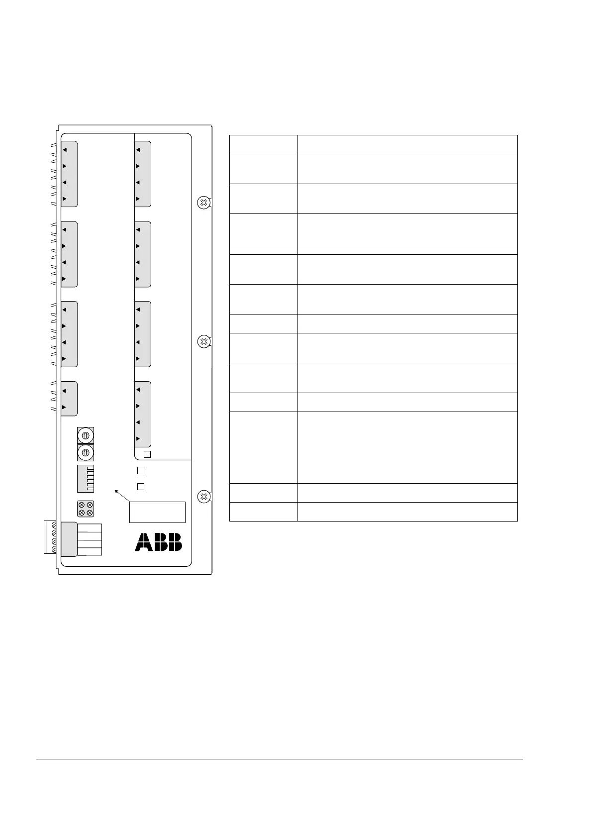
Designation Description
V1…V8
(CH1…CH4)
Fibre optic links to inverter modules 1…4.
V9, V10
(CNTL 1)
Fibre optic link to RDCU drive control unit.
V11, V12
(CNTL 2 OR
DDCS (PC))
Fibre optic link (DDCS) to PC for controlling the
operation of the datalogger and for transferring
collected data to PC.
V13, V14
(TRIGGER)
Connection for external testing equipment
(datalogger trigger pulse input/output).
V21…V36
(CH5…CH12)
Fibre optic links to inverter modules 5…12. Only
available with APBU-44CE.
S1, S2 DDCS node address for PC connection.
S3 DIP switches for optical power setting and memory
backup battery.
“RXD” LED Indicates data being received from RDCU drive
control unit.
“TXD” LED Indicates data being sent to RDCU drive control unit.
“BAT” LED Indicates that memory backup battery voltage is OK
(higher than 2.8 V). The LED is off if
• battery voltage is below 2.8 V,
• battery is switched off, or
• APBU-44C(E) is not powered.
“PWR” LED Indicates that 5 V power to on-board logic is OK.
X1 24 V DC power input.