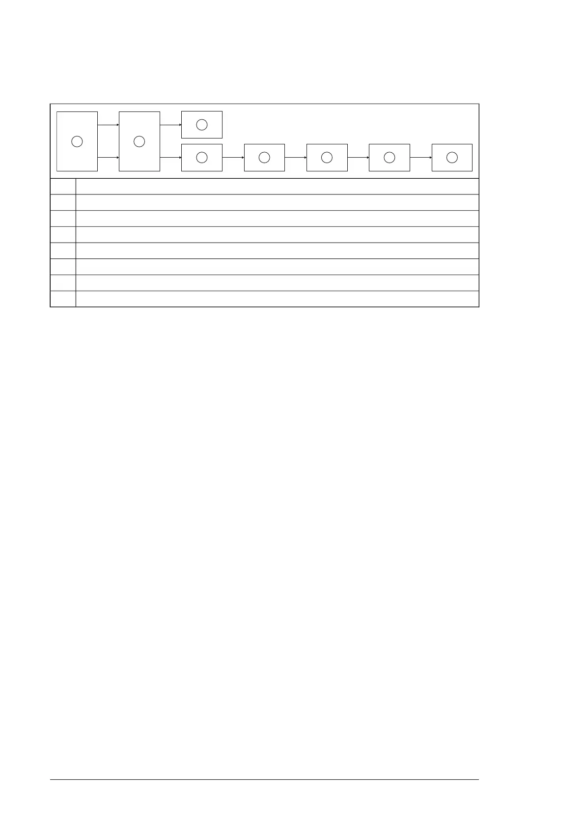
Diagram 4: ACS880-17/17LC/37/37LC drives, frames n×R8i + n×R8i and frame R11
Emergency stop button1
FSO module, and FSE module (if used)2
Drive STO3
Auxiliary safety relay4
Charging contactor5
Auxiliary safety relay6
Main contactor or main breaker7
Main contactor or main breaker8
Note: Only some variants have two main contactors or main breakers.
■ Relevant failure modes
Relevant failure modes are:
• the main contactor/breaker does not open when requested. (All contactor/breaker failures
are considered dangerous.)
• the FSO module detects any open circuits, short circuits and redundancy failures of the
emergency stop input signal wirings. Similarly, it detects redundancy failures of the
emergency stop button when the request is on.
• internal failures of the emergency stop button, the FSO and FSE modules and the STO
function in the drive.
These failures are included in the failure rate value of the function.
■ Fault exclusions
Fault exclusions (not considered in the calculations):
• any short and open circuits in the cables of the safety circuit inside the cabinet
• any short and open circuits in the cabinet terminal blocks of the safety circuits.
■ Operation delays
Emergency stop total delay and fault reaction response time (includes the response time
of the drive STO):
• Stop category 0: less than 500 ms
• Stop category 1: Emergency stop ramp time + possible STO delay settings + less than
500 ms.
Note: If you use a safety pulse encoder, you must add the delays of the encoder when
defining the total response time for the safety function and the fault reaction function.
Ambient conditions
For the environmental limits for the safety functions and the drive, refer to the hardware
manual of your drive, and to FSO and FSE-31 module user's manuals.
70 Technical data

 Loading...


