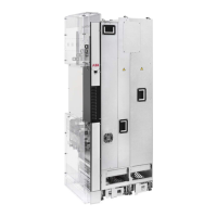
Connect the intermediate control cables between the drive module and the control unit to
the ZBIB board terminals at the rear side of the control unit adapter.
5
• Pull the fiber optic, power supply and STO cables through the hollow back frame of the
control unit.
• Connect the cables to the ZBIB terminals.
ZBIBQOIA
INU ZBIB
V1 V2
ISU ZBIB
V20 V21
2
1
X7 (STO1)
INU STO
X8 (STO2)
X3X2
V2V2
V1V7
V21V8
V22V13
Attach the control unit, for example, to a DIN rail.6
Ground the outer shields of all external control cables 360° at the cabinet entry.7
Ground the pair-cable shields of external control cables to a grounding clamp below the
control unit. Leave the other end of the shields unconnected or ground them indirectly via a
high-frequency capacitor with a few nanofarads, eg 3.3 nF / 630 V.
8
Connect the conductors of external control cables to the appropriate terminals of the control
unit. See section Default I/O diagram of the drive control unit (ZCU-1x) (Page 16).
9
Wire the optional modules if included in the delivery.10
Connect the control panel cable to connector X13 of the control unit.11
Put the control panel holder on the control unit. Put the control panel to the recess if removed.12
Default I/O diagram of the drive control unit (ZCU-1x)
DescriptionTermConnection
XPOW External power input
24 V DC, 2 A min. (without optional modules)
+24VI
GND
16 EN – Quick installation and start-up guide
EN
DA
DE
ES
FI
FR
IT
NL
PL
PT
SV
TR
ZH

 Loading...