Do you have a question about the ABB CMS-700 and is the answer not in the manual?
Manual storage guidelines.
Copyright statement for the manual.
Disclaimer regarding document information and usage.
Trademark information for ABB.
Explanation of symbols used in the manual.
Instructions for cleaning the device.
Requirements for connecting the device to mains.
Safety procedures for mains connection/disconnection.
General safety precautions and warnings.
Guidelines for proper disposal of the device.
Information on service and warranty.
Describes the purpose and application of the CMS-700.
Details the reset button and status/network LEDs.
Lists the technical details and parameters of the CMS-700.
Shows the physical dimensions of the control unit.
Explains how measurements are taken for mains and branches.
Details how to set up and configure events.
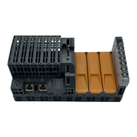
Describes the parts and connections of the control unit.
Details different types of CMS sensors and their mounting.
Information about the current transformer.
Details about the CMS flat cable and its lengths.
Describes the connector set for flat cables.
Conditions for product warranty.
Specifies requirements for installation personnel.
Instructions for mounting the unit on a DIN rail.
Steps for assembling connectors on the flat cable.
Guidance on correct cable positioning for sensors.
How to mount sensors with twin terminals.
Instructions for mounting sensors on DIN rails.
How to mount sensors using cable ties.
Final steps for connecting sensors to the control unit.
Wiring instructions for connecting to mains.
Wiring procedures for disconnection/connection.
Wiring diagram for three-phase systems with neutral.
Wiring diagram for single-phase systems.
Setting up static IP for initial access.
Notes on DHCP access for commissioning.
Connecting the unit via a router.
Steps for direct LAN connection.
How to access the Web UI using hostname.
Steps for configuring and selecting IPv4 properties.
Explains the initial login screen and credentials.
Overview of the Web UI structure and menus.
Configuration options for mains settings.
Configuration for branch settings, including adding sensors.
Setting up and configuring events and alarms.
Configuration for exporting data via email or FTP.
Configuration of email and FTP server details.
Configuration of network IP settings.
Configuration of SNMP service versions and parameters.
Configuration of Modbus TCP and RTU settings.
Uploading, generating, and importing SSL certificates.
Selecting the user interface language.
Configuring device time via manual setting or NTP.
Changing the device password for security.
Instructions for updating the device firmware.
Options for restarting, restoring defaults, or shutting down the device.
General overview of the Home menu features.
Viewing online and historical data for mains.
Viewing online and historical data for branches.
Visualizing energy consumption for mains, groups, and branches.
Displaying and exporting event occurrences.
Introduction to the Modbus protocol.
Details the structure of Modbus RTU frames.
How to communicate with CMS via RS-485.
Lists common Modbus error codes.
Explains data register formats and special values.
Special values for branch power and energy.
Commands for holding and resetting measurements.
Command to activate sensor LED blinking for diagnostics.
Commands for starting/stopping sensor LED blinking.
Applicable items for SNMP protocol.
Error codes for branch current values.
Special meanings for calculated branch power and energy.
Information on MIB files for SNMP.
Examples of using snmpget program.
Registers for current measured data.
Registers for minimum measured values.
Registers for maximum measured values.
Registers for hold values during measurement requests.
Information about sensor serial numbers and bus lines.
Polarity settings for DC sensors.
Registers for calculated sensor values (Power, Energy).
Registers for control functions like timeout and UI mode.
Mapping for branch names, groups, and phases.
Mapping for alarm status and thresholds.
Registers for mains measurements like voltage, current, power factor.
| Brand | ABB |
|---|---|
| Model | CMS-700 |
| Category | Control Unit |
| Language | English |