—
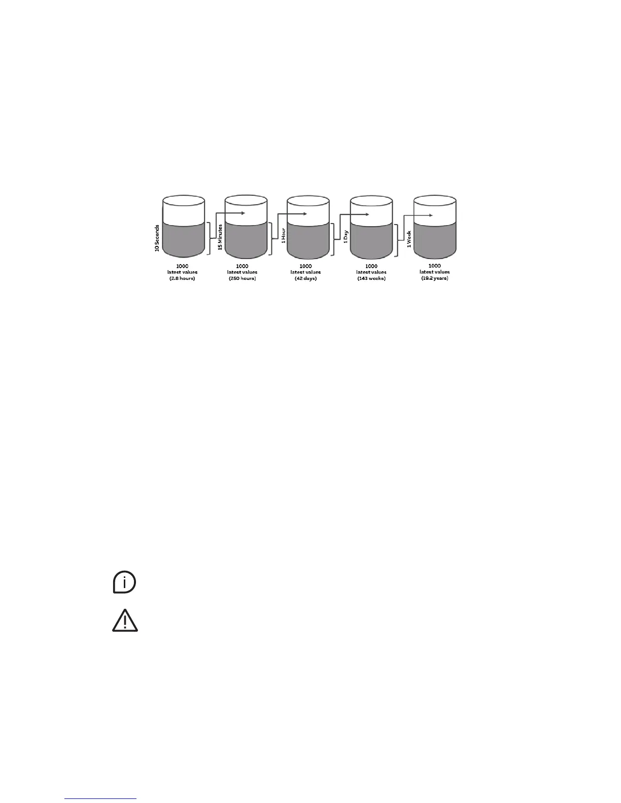
Memory architecture
The measured values of the main power network and those of the 96 outputs
are stored in the following memory areas:
Stored values
Mains
• Voltage [V]: L1, L2, L3
• Current [A]: L1, L2, L3, N
• Power factor [-]: L1,L2,L3
• THD U [%]: L1, L2, L3
• THD I [%]: L1, L2, L3, N
• Active power[W]: L1, L2, L3
• Apparent power [VA]: L1, L2, L3
• Reactive power [VAR]: L1, L2, L3
• Active power summation [W]
• Apparent power summation [VA]
• Reactive power summation [VAR]
• Active energy [Wh]: L1, L2, L3
• Apparent energy [VAh]: L1, L2, L3
Branches
• Current (TRMS, AC, DC) [A]
• Active power [W]
• Active energy [Wh]
These values of the respective stacks can be exported as a CSV-file
and pulled into an FTP or sent by e-mail.
Time reference
The measured values are provided with a UTC time stamp. UTC (Universal Coordinated Time)
stands for the location-independent world time in seconds.