ANR96 - USER MANUAL
-17-
6.2) VOLTAGE INPUTS
ANR96 can measure voltages up to a maximum 600 Vrms between phase-phase, further
that value it is imperative to use voltage transformer. When using voltage transformer, make
sure to respect the input and output polarities.
Use cables with maximum cross-section of 2.5mm
2
attach them to the voltage measurement screw
terminals.
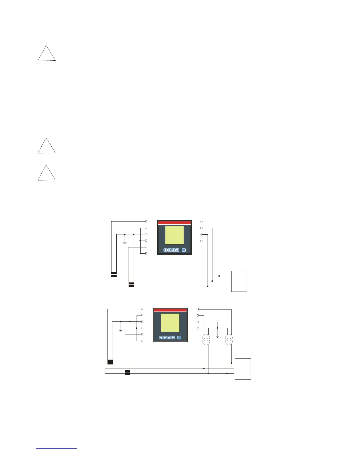
Connect the instrument following up the wiring diagrams described on chapter 6.4).
ANR96 was developed and tested in accordance with IEC 348 class 1 standards for operating
voltages up to 600 Vac rms.
6.3) CURRENT INPUTS
Connect the instrument following up the wiring diagrams described on chapter 6.4).
WARNING: before connecting the current inputs to the terminals of the instrument are
advised that the maximum allowable current input must be and not exceed 5A.
WARNING: to prevent accidentally disconnection of the current input, ANR96 is equipped
with screw able current input, in order to avoid negligence, operator must first shutdown the
system and short circuit the secondary wiring of the current transformer, if used, and
unscrews the current input terminals.
6.4) WIRING DIAGRAM