EasyManua.ls Logo

ABB ACF5000 User Manual

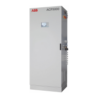
ABB ACF5000
200 pages
To Next Page IconTo Next Page
Page #1 background imageLoading...
Page #1 background image
ABB MEASUREMENT & ANALYTICS | OPERATING INSTRUCTION
ACF5000
Multi-component FTIR analyzer system
Measurement made easy

Table of Contents

Questions and Answers:

ABB ACF5000 Specifications

General IconGeneral
Operating temperature-20 °C to +45 °C (-4 °F to +113 °F)
Power supply100 to 240 VAC, 50/60 Hz or 24 VDC
Response timeTypically < 60 s (application dependent)
Protection RatingIP65
Measurement principleFTIR (Fourier Transform Infrared)
Communication interfacesEthernet
Data storageInternal memory for data logging
EnclosureIP65
Output4-20 mA, digital outputs
Measured componentsMultiple gases including CO, CO2, NO, NO2, SO2, H2O, NH3, HCl, HF, CH4, N2O
Typical measured gasesSO2, NO, NO2, N2O, CO, CO2, NH3, H2O, CH4, HCl, HF, O2, and many VOCs

Summary

Preface

Content of the operating instruction

Describes what the operating instruction covers regarding installation, commission, operation, and maintenance.

System documentation

Lists the components included in the system documentation package.

Further information

Provides contact details for ABB online resources and service support.

Identification of safety instructions in this operating instruction

Letters and numbering used in this operating instruction

Explains the conventions and symbols used within the manual.

Safety instructions

Intended use

Describes the designed purpose of the ACF5000 analyzer system.

Requirements for safe operation

Outlines general principles for safe and efficient device operation.

Personnel qualifications

Specifies the required expertise for personnel working on the device.

Special information and precautions

Lists essential safety considerations and precautions to observe.

National regulations

Refers to applicable national regulations that should be followed.

Device safety and safe operation

Protective conductor terminal

Details the requirement to connect the protective ground conductor first.

Danger of a disconnected protective ground conductor

Explains the hazards associated with an interrupted protective ground conductor.

Dangers involved in opening the covers

Warns about potential exposure to current-bearing components when covers are removed.

Dangers involved in working with an open device

Emphasizes that work on an open device must be done by trained personnel.

When safe operation can no longer be assured

Defines conditions under which the device should be taken out of operation.

Safety instructions for handling the analyzer system

Safety instructions for handling the analyzer system with integrated FID

Safety instructions for handling the FTIR spectrometer

Safety instructions for working with poisonous gases

Description of the analyzer system

Application and function of the analyzer system

Explains the system's purpose, operational principles, and measuring method.

Options

Validation

Describes a validation unit for confirming spectrometer adjustment validity.

Total carbon measurement

Mentions the incorporation of a Flame Ionization Detector (FID) for VOC measurement.

Display and signal processing

Covers system controller design for emissions and process measurement.

Components of the analyzer system

Assemblies in the analyzer cabinet

Lists the primary assemblies located within the analyzer cabinet.

Option "Hydrogen monitoring of the analyzer cabinet"

Function

Describes the safety feature for FID systems to prevent ignitable mixtures.

Scope of supply and delivery

Lists the components included with the hydrogen monitoring option.

Installation

Details the installation process for the hydrogen monitoring option.

Preparation for installation

Selection of the sampling point, installation of the wall tube

Details how to choose and install the sampling point and wall tube.

Installation of the wall tube with mounting flange

Requirements for the installation site of the analyzer cabinet

Short gas paths

Discusses the importance of proximity to the measuring location for short dead times.

Protection from adverse ambient conditions

Lists environmental factors requiring protection for the analyzer cabinet.

Climatic conditions

Specifies the acceptable ambient temperature and humidity ranges for operation.

Installation site

Space requirement

Details the necessary clearances around the analyzer cabinet.

Floor

Specifies requirements for the floor at the installation site.

Sample gas inlet conditions

Operating gases and test gases

FTIR spectrometer

Lists the required gases for the FTIR spectrometer's operation.

FID

Lists the required gases for the Flame Ionization Detector (FID).

Oxygen sensor

Instrument air

Compressed air for back-purging

Power supply

Uninterruptible power supply (UPS)

Describes the specifications for an optional Uninterruptible Power Supply.

Service socket

Details the specifications of the service socket.

Fuses

Dimensions, weights and noise level

Weights

Lists the weights of various analyzer system components.

Noise level

Specifies the noise levels generated by the fan and air conditioner.

Scope of supply and delivery

Standard scope of supply and delivery

Lists the basic components included in the standard delivery.

Included with delivery if ordered

Lists optional components that may be included with delivery.

2nd measuring location option

Details the components included for the 2nd measuring location option.

"Hydrogen monitoring of the analyzer cabinet" option

Lists components for the hydrogen monitoring option.

Material required for the installation (not supplied)

Gas sampling

Lists materials needed for gas sampling installation.

Gas lines

Lists materials required for various gas lines.

Power supply lines

Lists materials for power supply and connecting cables.

Signal lines

Analog outputs

Describes shielded cables for analog outputs.

Analog inputs

Describes shielded cables for analog inputs.

Digital outputs

Describes cables for digital outputs.

Digital inputs

Describes cables for digital inputs.

Data lines

Describes cables for data communication (Modbus, Profibus, Ethernet).

Resistance thermometer

Describes cables for Pt100 resistance thermometers.

Assembly

Installation

General notices

Provides general recommendations and prerequisites for installation.

Installing the analyzer cabinet

Providing the foundation

Details requirements for the concrete base or frame for cabinet installation.

Unpacking the analyzer cabinet

Describes the procedure and precautions for unpacking the analyzer cabinet.

Installing the analyzer cabinet

Removing transport protection in the analyzer unit

Describes the process of removing transport protection elements.

"2nd measuring location" option

Installing the electrical distributor cabinet

Details the installation of the distributor cabinet for the second location.

Installing the heated switchover valve

Describes the installation of the heated switchover valve.

Installing the gas sampling probe and filter unit

Installing the gas sampling probe and filter unit

Provides detailed steps for installing the probe and filter unit.

Probe tube types

Probe tube type 40

Details specifications for probe tube type 40.

Probe tube type 42

Details specifications for probe tube type 42.

Installing the sample gas line

Installing the sample gas line

Provides guidelines and precautions for laying the sample gas line.

Installing the operating gases

Installing the instrument air supply

Details the connection requirements for the instrument air supply.

Installing the test gas cylinders

Describes the setup and placement of test gas cylinders.

Gas line connection

Provides guidelines for connecting various gas lines properly.

Combustion gas, Waste gas, and Purging gas

Combustion gas for the FID

Instructions for connecting combustion gas for the FID.

Waste gas

Guidelines for the proper discharge of waste gas.

Purging gas for gas extraction probe

Describes connecting the purge gas line for the probe.

Compressed air supply for back-purging the gas extraction probe (option)

Details compressed air supply for back-purging the probe.

Connecting the electrical leads

Description of the signal inputs and outputs

Details signal connections including analog, digital, and network interfaces.

Connecting the electrical leads

Connecting the signal lines

Describes how to lay and connect signal lines properly.

Connect power supply

Commissioning

Recommissioning

Outlines steps to restart the analyzer system after a shutdown.

Start of the measurement

FID restart

Details the restart procedure for the Flame Ionization Detector (FID).

Heating-up phase, connect supply gases

Describes connecting supply gases and the initial heating phase.

Flame ignition

Operation

Display and operation unit

Describes the components of the display and operation unit.

Operating modes of the display and operation unit

Explains the measuring mode and menu mode operations.

Display

The display

Details the display structure, resolution, and areas.

Message display

Message display functions

Explains the functions of the blinking message display.

Display of status messages

Describes how status messages are displayed on the screen.

Status LEDs

Status LEDs

Explains the meaning of the Power, Maint, and Error status LEDs.

Numeric keypad

Numeric keypad

Describes the layout and function of the numeric keypad.

Entering text with the numeric keypad

Explains how to use the numeric keypad for text entry.

Cancel keys

Cancel keys

Describes the function of the Back and Meas keys.

Softkeys

Softkeys

Explains the concept of softkeys and their interaction with the screen.

The softkeys in measurement mode

Details the softkey functions available in measurement mode.

The softkeys in menu mode

Representation of entries in this operating instruction

Text entry

Entering text

Describes the process and characters available for text entry.

Softkeys in the input mode

Explains softkey functions during text input.

Softkeys in edit mode

Explains softkey functions during text editing.

Operating by value input

Value input

Describes entering values using the numeric keypad during measurement.

Operating by key entry

Key entry

Describes making key entries by pressing numeric keys.

Password protection

Elements of password protection

Lists the three elements of password protection: level, group, and password.

Password level

Explains how password levels are assigned to menu items.

User group

Defines user groups and their access entitlements.

Password

Describes the password format and entry method.

Factory setting

Shows the default password settings for different user groups.

Password management and privileges

Viewing menu items

Explains that all users can view menu items without a password.

Changing menu items

Describes changing menu items based on password level and group authorization.

Change privilege

Explains user authorization for making changes to menu items.

Duration of the change privilege

Describes how long the privilege to make changes remains active.

Change password

Refers to the section describing how to change passwords.

Blocking operation

Blocking operation using the function block configuration

Explains how to block access to the analyzer system via function blocks.

Access denied

Shows the message displayed when access to the device is blocked.

Blocking operation using password protection

Explains how to protect menu access with a password.

Operating the analyzer system

Local HMI operation

Describes operation using the local Human-Machine Interface (HMI).

Remote HMI operation

Describes operation using a remote HMI via Ethernet.

Preference of an HMI

Explains how HMI preference is determined by password levels.

Web page operation

Functions

Lists functions that are exclusively accessible via a web page.

Access and operation

Details browser requirements and access procedures for web page operation.

Menu structure

Menu structure

Shows the hierarchical organization of the analyzer system's menus.

Password levels

Explains password level assignments for menu items.

Display of measured value

HMI display

Describes how measured values are displayed on the HMI screen.

Webpage display

Describes how measured values are displayed via the web page.

Adjustment: Basics

Controlling the adjustment

Explains the three methods for controlling the adjustment process.

Starting the adjustment

Describes how to initiate the adjustment process.

Wait until the warm-up phase has ended

Notes that adjustment should only start after the warm-up phase.

Plausibility check during adjustment

Explains plausibility checks that cancel adjustment if values are implausible.

Status signal

Describes the 'Maintenance mode' status signal during adjustment.

Manual adjustment

Definition

Defines manual adjustment as separate zero and span adjustments.

Test gas infeed

Describes starting the test gas supply.

Waiting period following manual adjustment

Explains the stabilization time after automatic adjustment.

Adjustment data

Refers to section for configuring manual adjustment data.

Adjust analyzer system manually

Refers to procedure for carrying out manual adjustment.

Automatic adjustment

Definition

Defines automatic adjustment as zero and endpoint adjustment after starting.

Test gas infeed

Describes automatic test gas feed via solenoid valves.

Starting the automatic adjustment

Explains how automatic adjustment is initiated (clock, signal, manual).

Internal start

Describes automatic adjustment starting cyclically based on the internal clock.

External start

Describes automatic adjustment starting via an external control signal.

Manual start

Describes manual initiation of automatic adjustment.

Automatic adjustment start and cancel

Message display

Describes messages displayed during automatic adjustment.

Waiting period following automatic adjustment

Explains the stabilization time after automatic adjustment.

Adjustment data

Refers to sections for configuring FID and O2 sensor automatic adjustment.

Adjustment methods

Adjustment method

Explains defining adjustment of components and ranges jointly or individually.

Single adjustment

Describes individual adjustment for each component/range.

Common adjustment

Describes joint adjustment across ranges for each component.

Substitute gas adjustment

Explains adjustment procedures when test gases are unavailable.

Overview

Setting the adjustment method

Explains how to set the adjustment method for different control types.

FID: Conversion of concentration data

Various units for concentration details

Lists common units for organic carbon compound concentration measurements.

Examples for the conversion of units and concentration details

Provides examples for converting units and concentration details.

Adjustment: Configuration

Configuring the automatic reference FTIR

Details how to configure the automatic recording of FTIR references.

Procedure

Automatic Adjustment Check (AAC): Configuring the time sequence

Function

Explains the purpose of configuring the Automatic Adjustment Check (AAC).

Menu path

Provides the navigation path to configure AAC time sequence.

Display

Shows the configuration screen for the AAC time sequence.

Procedure

Details the parameter settings for the AAC time sequence.

Parameter Explanation

Automatic Adjustment Check (AAC): Settings and export of the QAL3 data

Function

Explains that AAC settings and QAL3 data export are made via the web page.

Menu path

Provides the navigation path for QAL3 settings.

Password

Mentions the password requirement to access the QAL3 submenu.

Display

Shows the QAL3 configuration screen.

Measurements

Describes how to view AAC results and check automatic adjustment.

Export components

Explains how to export AAC results for measuring components.

Edit components

Settings

Configuring the Automatic Drift Check (ADC)

Function

Explains the optional cyclical drift check with automatic test gases.

Menu path

Provides the navigation path for configuring the Automatic Drift Check.

Display

Shows the configuration screen for the Automatic Drift Check.

Configuring gas port

Describes selecting the test gas inlet for ADC configuration.

Parameter Explanation

Configuring the ADC operating mode

Starting the gas port immediately

Configuring manual adjustment

Menu path

Provides the navigation path for configuring manual adjustment.

Test gas concentration

Explains setting zero and span test gas concentrations for manual adjustment.

Adjustment method

Describes selecting the adjustment method for manual adjustment.

Configuring automatic adjustment of the FID

Function

Explains the configuration of automatic adjustment with test gas for FID.

Menu path

Provides the navigation path for FID automatic adjustment.

Display

Shows the configuration screen for FID automatic adjustment.

Procedure

Details parameter settings for FID automatic adjustment.

Parameter Explanation

Configuring automatic adjustment of the oxygen sensor

Function

Explains the configuration of automatic adjustment for the oxygen sensor.

Menu path

Provides the navigation path for oxygen sensor automatic adjustment.

Display

Shows the configuration screen for oxygen sensor automatic adjustment.

Procedure

Details parameter settings for oxygen sensor automatic adjustment.

Parameter Explanation

Check time conflicts of the automatic processes

Automatic processes in the analyzer system

Lists configurable automatic processes: reference, adjustment, drift check.

Menu path

Provides the navigation path to check time conflicts.

Password

Mentions the password requirement to access this submenu.

Display

Shows the calendar view to check scheduling conflicts.

Output current response

Menu path

Provides the navigation path for output current response configuration.

Output current response

Describes signal behavior at current outputs during adjustment.

Adjustment: Operation

Carrying out manual reference

Describes how to create a manual reference for the FTIR spectrometer.

Procedure

Displaying the status of the last reference

Menu path

Provides the navigation path to view the status of the last reference.

Procedure

Describes how to display the status of the last reference.

Displaying diagnosis values of the reference measurement

Function

Explains how to display the last reference measurement's diagnosis values.

Menu path

Provides the navigation path to view diagnosis values.

Procedure

Describes how to display the reference measurement diagnosis values.

Saving the reference as an initial reference

Function

Explains saving a manual reference as an initial reference.

Menu path

Provides the navigation path to save the reference.

Procedure

Describes how to save the reference as an initial reference.

Start Automatic Adjustment Check (AAC) manually

Function

Explains that the automatic cyclic monitoring can be started manually.

Menu path

Provides the navigation path for starting AAC manually.

AAC cycle "split"

Describes the operation of the AAC cycle in 'split' mode.

AAC cycle "complete" or "complete & reference"

Carry out manual adjustment

Adjust analyzer module manually

Provides detailed steps for manually adjusting the analyzer module.

Manual start of automatic adjustment

Automatic adjustment

Explains the types of automatic adjustment: zero point, end point, or jointly.

Manual start of automatic adjustment

Details how to manually start automatic adjustment.

Cancel automatic adjustment manually

Describes how to cancel automatic adjustment using the STOP softkey.

Configuration: Component functions

Configuring measuring range

Explains how to configure the measuring ranges for components.

Changing measuring range limits

Menu path

Provides the navigation path for changing measuring range limits.

Selection

Describes that all configured measuring ranges are displayed.

Procedure

Details steps to change measuring range limits.

Measures after changing the measuring range limits

Notes actions required after changing measuring range limits.

Change number of decimal places

Menu path

Provides the navigation path for changing decimal places.

Selection

Describes that all configured measuring ranges are displayed.

Procedure

Details steps to change the number of decimal places.

Number of decimal places

Shows a table relating measuring span to decimal places.

Add measuring range

Menu path

Provides the navigation path to add a measuring range.

Selection

Describes how to add a measuring range if 'Free' is shown.

Procedure

Details the steps to add a new measuring range.

Delete measuring range

Menu path

Provides the navigation path to delete a measuring range.

Selection

Describes which measuring ranges can be deleted.

Procedure

Details the steps to delete a measuring range.

Configuring automatic measuring range switching

Menu path

Provides the navigation path for automatic measuring range switching.

Lower threshold, upper threshold

Explains thresholds for automatic switching between measuring ranges.

Assigned measuring ranges

Describes parameterizing ranges for automatic switching.

Status

Explains how to activate or deactivate automatic measuring range switching.

Example for auto-ranging

Illustrates automatic range switching with an example.

Procedure

Details the steps for configuring automatic measuring range switching.

Configuring filter

Menu path

Provides the navigation path for filter configuration.

Procedure

Details filter parameter settings like T90-1 and T90-2.

Non-linear filter

Discusses settings and recommendations for non-linear filters.

Active component selection

Menu path

Provides the navigation path for active component selection.

Active component

Explains selecting a single active component for measurement.

Procedure

Details the steps for selecting the active component and measuring range.

Configuring limit monitoring

Menu path

Provides the navigation path for limit monitoring configuration.

Selection

Lists all available limit value monitors.

Procedure

Details parameter settings for limit monitoring (Direction, Threshold, Hysteresis).

Standard configuration

Notes that limit value monitoring is often factory-set.

Configuring FTIR limit monitoring

Function

Explains FTIR limit monitoring configuration for exceeding limit values.

Menu path

Provides the navigation path for FTIR limit monitoring.

Procedure

Details parameter settings for FTIR limit monitoring.

Configuring dry base and O2 reference

Correcting the measurement value

Explains converting concentrations to dry base or O2 reference.

Menu path

Provides the navigation path for correction settings.

Procedure

Details how to activate and configure correction functions.

Display of measured value

Explains how corrected values are indicated on the display.

Changing module name

Menu path

Provides the navigation path for changing module names.

Module name

Explains how to enter a name related to the measuring point.

Monolingual or bilingual

Describes language options for module names.

Text length

Specifies the length limits for module name text.

Entering the module name

Refers to general text entry procedures for module names.

Configuration: System functions

Setting time zone, date and time

Details how to configure the analyzer system's time settings.

Selecting user interface language

Menu path

Provides the navigation path for selecting the user interface language.

Language selection

Explains the available user interface languages (German and English).

Change password

Menu path

Provides the navigation path for changing passwords.

Password protection

Refers to basic information on password protection.

Factory setting

Shows the default password settings for user groups.

Procedure

Details the steps required to change a password.

Blocking operation

Menu path

Provides the navigation path for blocking analyzer system operation.

Blocking operation

Explains how operation can be blocked via password protection.

Setting system modules

Menu path

Provides the navigation path for setting system modules.

Function

Explains the need to configure added or removed system modules.

Analyzer modules and external I/O devices

Discusses how analyzer and I/O devices are identified by serial number.

I/O modules

Specifically addresses I/O modules and their automatic identification.

Serial number

Explains the structure and use of serial numbers for module identification.

Unknown system module

Add system module

Add a new analyzer module or a new I/O device

Details the procedure for adding analyzer modules or external I/O devices.

Add a new I/O module

Details the procedure for adding new I/O modules.

Replace system module

Uninstallation and reinstallation of the same system module

Explains reinstalling an existing system module after uninstallation.

Delete system module

Sequence when removing system modules

Outlines the mandatory sequence for removing system modules.

Delete an existing system module without replacement

Details the steps for deleting a system module without replacement.

Save configuration

Menu path

Provides the navigation path for saving configuration data.

Automatic saving of the configuration

Explains the automatic saving of configuration data.

Save configuration manually

Describes how to save the configuration database manually.

Backup

Explains how to create a backup of the current configuration.

Configuring status signals

Menu path

Provides the navigation path for configuring status signals.

Function

Explains that status signal configuration is usually set at the plant.

Selection

Lists the available status signal types: individual and overall.

Configuring Ethernet connection

Menu path

Provides the navigation path for Ethernet connection configuration.

Function

Explains system integration via Ethernet using TCP/IP protocol.

Parameter

Details DHCP settings and required parameters.

Address

Explains the requirement to query IP addresses from the system administrator.

Configuring Modbus connection

Menu path

Provides the navigation path for Modbus connection configuration.

Function

Explains system integration via Modbus protocol (RS232, RS485, Ethernet).

Parameter

Details Modbus protocol support and standard settings.

Configuring Profibus

Menu path

Provides the navigation path for Profibus configuration.

Parameter

Details Profibus parameters like address, type, baudrate, and map.

Configuring Bus I/Os

Menu path

Provides the navigation path for Bus I/O configuration.

Number of Bus I/Os

Explains the impact of changing the number of Bus I/Os.

Parameter

Details Bus I/O parameters and their functions.

Configuration: Display functions

Display features

States that the analyzer system screen is freely configurable in measurement mode.

Display elements

Lists the types of display elements available (quantities, inputs, entries).

"Pages"

Explains that the screen is divided into pages for displaying elements.

System pages (standard layout)

Describes the default system page layout with measured values.

User pages

Function blocks as sources

Describes using function blocks as sources for display elements.

Display element positioning on the screen

Explains how display elements can be represented and positioned.

Display overview

Display overview

Shows the list of configured display pages and their properties.

Parameter

Details parameters for the display overview (Page, Pos., Description).

Softkeys in the screen overview

Explains the functions of softkeys used in the screen overview.

Page overview

Page overview

Shows the list of screen pages and their status (On/Off).

Parameter

Details parameters for the page overview (No., Name, Assignment, Type).

Page overview softkeys

Explains the functions of softkeys used in the page overview.

Parameter overview

Parameter overview

Details parameters for individual display elements.

Parameter

Lists and explains parameters like Name, Test point, Source, Page, Position.

User page configuration

User page configuration

Details the steps for configuring custom user pages.

Moving a display element from one page to another

Moving a display element from one page to another

Provides steps to move display elements between different pages.

Moving a display element within a page

Moving a display element within a page

Provides steps to move display elements within the same page.

Configuring the bar display or point display

Configuring the bar display or point display

Details the configuration process for bar and point display elements.

Value input

Configuring the value input

Explains configuration of value input display elements.

Description

Describes the source of the value input display element.

Configuration

Lists parameters to configure for value input.

Procedure

Explains how values are entered during measurement.

Configuring value input

Configuring value input

Details the steps for configuring value input.

Key entry

Configuring key entries

Explains configuration of key entries for display elements.

Description

Describes the source of the key entry display element.

Configuration

Lists parameters to configure for key entries.

Procedure

Explains how key entries are made during measurement.

Configuring key entries

Configuring key entries

Details the steps for configuring key entries.

Maintenance

General notices

Provides general safety notices for maintenance work.

Visual inspection

Visual inspection

Details the internal view of the analyzer cabinet and checks.

Cleaning the analyzer cabinet

Notes on cleaning the analyzer cabinet

Provides instructions for cleaning the analyzer cabinet interior and exterior.

Seal integrity test

Complete seal integrity test of the analyzer system

Describes complete seal integrity tests reserved for certified personnel.

Simplified seal integrity test of the sample gas path

Describes a simplified leak test for the sample gas path.

When must the simplified seal integrity test be performed?

Lists conditions requiring a simplified seal integrity test.

Simplified seal integrity test via oxygen measurement

Details the oxygen measurement method for leak testing.

Simplified seal integrity test via FID

Other indications of leaks

Lists potential signs indicating leaks in the analyzer system.

FID: Seal integrity and functional checks

Seal integrity check of the combustion gas path

Details how to check the seal integrity of the combustion gas line.

Seal integrity check of the combustion gas supply line

Details checking the combustion gas supply line integrity.

Combustion gas supply from a central supply

Function test of the H2 safety valve

Maintenance switch

Function

Explains how to set the analyzer system to 'Maintenance' status.

Menu path

Provides the navigation path for the maintenance switch.

Display

Shows the interface for the maintenance switch.

Message

Describes messages related to the maintenance switch activation.

Emergency purging

Automatically switching to emergency purging

Explains automatic activation of emergency purging due to low temperatures.

Ending emergency purging manually

Details the procedure for manually ending emergency purging.

External trigger of the emergency purging

Explains how emergency purging can be triggered externally.

Monitoring the internal cabinet temperature

Automatic deactivation of internal heaters

Explains heater deactivation when cabinet temperature exceeds limit.

Message and status signaling

Describes status messages and signaling for temperature errors.

Activating heating manually

Details manual reactivation of heaters after temperature normalization.

Connecting gas paths and inserting validation cells

Function

Explains manual connection of gas paths for emitting test gases.

Gas path

Explains different gas paths like Zero gas, Drift port, and AAC cell.

Changing analog output current range

Method

Explains how to change analog output current ranges via parameter settings.

Changing current range

Describes the parameter used for changing the current range.

Selection

Lists the available choices for current ranges (0-20mA, 2-20mA, 4-20mA).

Current range limits

Specifies the limits for the output signal (0mA and 22mA).

Adjustment reset

What does the adjustment reset do?

Explains that adjustment reset returns settings to basic values.

When should an adjustment reset be performed?

Lists conditions for performing an adjustment reset.

Menu path

Provides the navigation path for adjustment reset.

Basic adjustment

What does the basic adjustment do?

Explains that basic adjustment resets the module to an initial state.

When should a basic adjustment be performed?

Lists conditions for performing a basic adjustment.

Check prior to a basic adjustment

Lists checks to perform before a basic adjustment.

Test gases

Mentions the requirement for zero and/or span test gases.

Carrying out the basic adjustment

Describes how basic adjustment is performed for a component.

Menu path

Provides the navigation path for basic adjustment.

FID: Standby/Restart

Menu path

Provides the navigation path for FID standby and restart.

Display of the operating condition of the FID

Shows the screen displaying the FID's operating condition.

The key operating data of the FID are displayed

Lists the key operating data displayed for the FID.

Definitions

Defines standby mode and fail-safe mode.

Putting the FID in standby mode

Setting FID back to measuring mode

FID in fail-safe status

Configuring saving of FTIR spectral data

Function

Explains how to configure whether FTIR spectral data is saved.

Menu path

Provides the navigation path for configuring spectral data saving.

Display

Shows the configuration screen for saving FTIR spectral data.

Configuring automatic back-purging of the gas extraction probe

Recommended program run for back-purging

Shows a diagram of the recommended program run for back-purging.

Function block application "Back purging"

Explains back-purging as a function block application.

Menu path

Provides the navigation path for configuring back-purging.

Procedure

Details setting automatic back-purging times via time encoder.

Replacing wearing parts

Before executing maintenance work...

Lists precautions before performing maintenance work.

Replacing wearing parts

Lists wearing parts and their recommended replacement cycles.

Spare parts information

Provides information on obtaining spare parts from ABB.

Replacing filter on the gas sampling probe

Wearing parts

Lists filter parts, item numbers, and replacement intervals.

Filter unit

Shows a diagram of the filter unit components.

Cleaning or replacing filters

Provides instructions for cleaning or replacing filter elements.

Filter replacement procedure

Replacing sample gas filter in the ASP block

Wearing parts

Lists sample gas filter parts and their replacement cycle.

Replacing the entire sample gas filter

Describes replacing the complete sample gas filter.

Cleaning or replacing sample gas filters

Provides instructions for cleaning or replacing sample gas filters.

Preparing to remove the filter, interrupting measuring mode

Details steps to prepare for filter removal.

Removing the filter

Describes the process of removing the filter from the ASP block.

Fitting the filter

Replacing filter in the compressed air main regulator (-J85)

Wearing parts

Lists the filter part and its replacement cycle.

Replacing the filter element

Details the process of replacing the filter element.

Preparing to remove the filter, interrupting measuring mode

Details preparation steps before replacing the filter.

Restoring measuring mode

Describes steps to return to normal operation after filter replacement.

Replacing filters in the sample gas pressure regulator

Wearing parts

Lists filter parts and their replacement cycle.

Replacing the filter

Details the process of replacing the filter.

Replacing filter cells in air purifier AU5

Wearing parts

Lists filter cell part number and replacement cycle.

Replacing filter cartridges

Details the procedure for replacing filter cartridges in the air purifier.

Replacing filter pad in the fan

Wearing parts

Lists filter pad part number and replacement cycle.

Replacing the filter pad

Details the procedure for replacing the fan filter pad.

Replacing the battery on the system controller

Wearing parts

Lists battery type and recommended replacement interval.

Replacing the battery on the system controller

Details the procedure for replacing the system controller battery.

Replacing pressure equalization screws

Wearing parts

Lists pressure equalization screw part number and replacement interval.

Replacing pressure equalization screws

Details the procedure for replacing pressure equalization screws.

Status messages, troubleshooting

Dynamic QR code

Explains the dynamic QR code feature and its application.

Handling

Describes how to use the QR code scanner and submit information.

Select QR code

Menu path

Provides the navigation path to display the QR code.

Procedure

Details steps to select and scan the QR code.

Recommended QR code scanner applications

Lists recommended QR code scanner applications for mobile devices.

Process status

Definitions

Defines terms related to process status.

Process status

Explains what process status includes.

Transgression of measuring range limits

Describes behavior when measured values exceed range limits.

Transgression of limit values

Describes status when measured values exceed set limit values.

System status: Status messages

Where are status messages generated?

Lists the sources where status messages are generated.

User-configured status messages

Explains the integration of user-defined status messages.

Status message processing

Describes how status messages are processed and displayed.

Status message display

Explains how status messages are displayed and acknowledged.

Entry of the status messages in the logbook

Describes how status messages are logged, excluding transient ones.

System status: Status signals

Overall or individual status

Explains the output configuration of status signals as overall or individual.

Overall status

Describes how status messages are issued as overall status indications.

Individual status

Describes how status messages are issued as individual status.

Individual status by analyzer module or sample component

Explains how individual status signals refer to analyzer system or components.

Status indication

Describes status indication using status LEDs.

Status message categories

Status messages not requiring acknowledgement

Describes messages that do not require operator acknowledgment.

Status messages requiring acknowledgment

Describes messages requiring acknowledgment but not intervention.

Status messages requiring acknowledgment and intervention

Describes messages needing acknowledgment and operator intervention.

Summary

Status message system

List layout

Explains the information contained in the status message list.

Status messages

Lists status messages with codes, text, and reaction/comment.

Status messages FTIR

List layout

Explains the structure of the FTIR status message list.

Status messages

Lists FTIR-specific status messages with codes and reactions.

Analyzer system: Troubleshooting

Display of measured value flashes

Describes issues related to measured value display.

Measured signal exceeds measuring range limits

Explains behavior when measured signals exceed range limits.

Display of measured value flashes alternating with --E--

Describes errors in measured signal processing.

Only mA display flashes alternating with --E--

Describes faults in the output current circuit.

Flow error

Addresses issues with gas lines, filters, and gas paths.

Temperature problem

Discusses temperature-related issues and warm-up phases.

Excessive air movement

Addresses drafts affecting the analyzer system.

Ambient temperature outside of permissible range

Discusses environmental temperature limits and protection.

FID: Troubleshooting

Temperature problem

Addresses issues with temperature sensors, heaters, and connections.

Unstable display of measured value

Covers causes like vibrations, leaks, and pressure issues affecting readings.

Loss of sensitivity

Mentions notifying service for loss of sensitivity.

Sample gas outlet pressure too high

Discusses issues with the sample gas outlet pressure.

Combustion air contaminated

Addresses problems related to contaminated combustion air.

Fluctuating process gas pressures

Discusses variations in process gas pressures.

Outgassing of hydrocarbons in the H2 safety valve

Addresses hydrocarbon outgassing related to the H2 safety valve.

Pressure regulator fault

Addresses issues with pressure regulators and set points.

Zero point drift

Discusses causes of zero point drift, such as contaminated lines.

Flame does not ignite

FID in fail-safe status

Notify service

Who should you contact for further help?

Provides contact information for local service representatives and ABB Service.

Before you notify service…

Lists information to check before notifying service.

When you notify service…

Lists information required when notifying service.

When you return the analyzer system to the service department…

Provides safety instructions regarding gas supply information for returns.

Decommissioning

Shutting down the analyzer system temporarily

Details the procedures for temporarily shutting down the analyzer system.

Packing the analyzer cabinet

Describes the procedures for packing the analyzer cabinet for transport.

Disposal

Notes for disposal

Provides information on proper disposal of the product and packaging.

Related product manuals