ACF5000 FTIR ANALYZER SYSTEM | OI/ACF5000-EN REV. A 35
Installing the analyzer cabinet
Refer to the "Requirements for the installation site" (see page 22)
Provision the "Required material" (see page 31).
Observe the "Arrangement diagram" in the system documentation.
Grounding via central grounding screw, route grounding cable
(≥ 10 mm
2
, AWG6 with "CSA version" option) through the M16 cable
gland provided in the right-hand cabinet wall for this purpose.
Removing transport protection in the analyzer unit
NOTICE Removing the transport protection immediately before commissioning the
analyzer system is highly recommended.
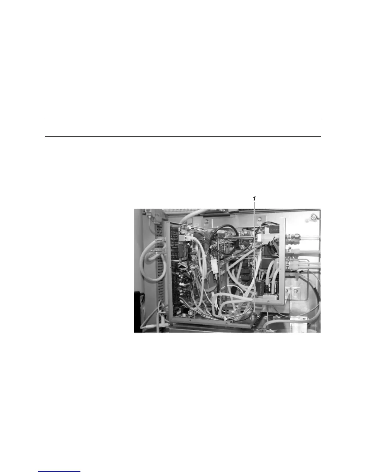
Removing the transport protection of the ASP block
The ASP block is fastened using a M8x80 transport protection bolt. This is
routed from above through a hole in the housing of the ACF5000 electronics
box AU1 and screwed into the ASP block.
1 Open the cover of the ACF5000 electronics box and take it out.
2 Using a 13 mm spanner, undo the transport protection bolt 1 and re-
move it together with the washer.
3 Remount the cover of the ACF5000 electronics box and close it.
4 Keep the transport protection bolt together with the washer for trans-
porting at a later time.