ACF5000 FTIR ANALYZER SYSTEM | OI/ACF5000-EN REV. A 143
Visual inspection
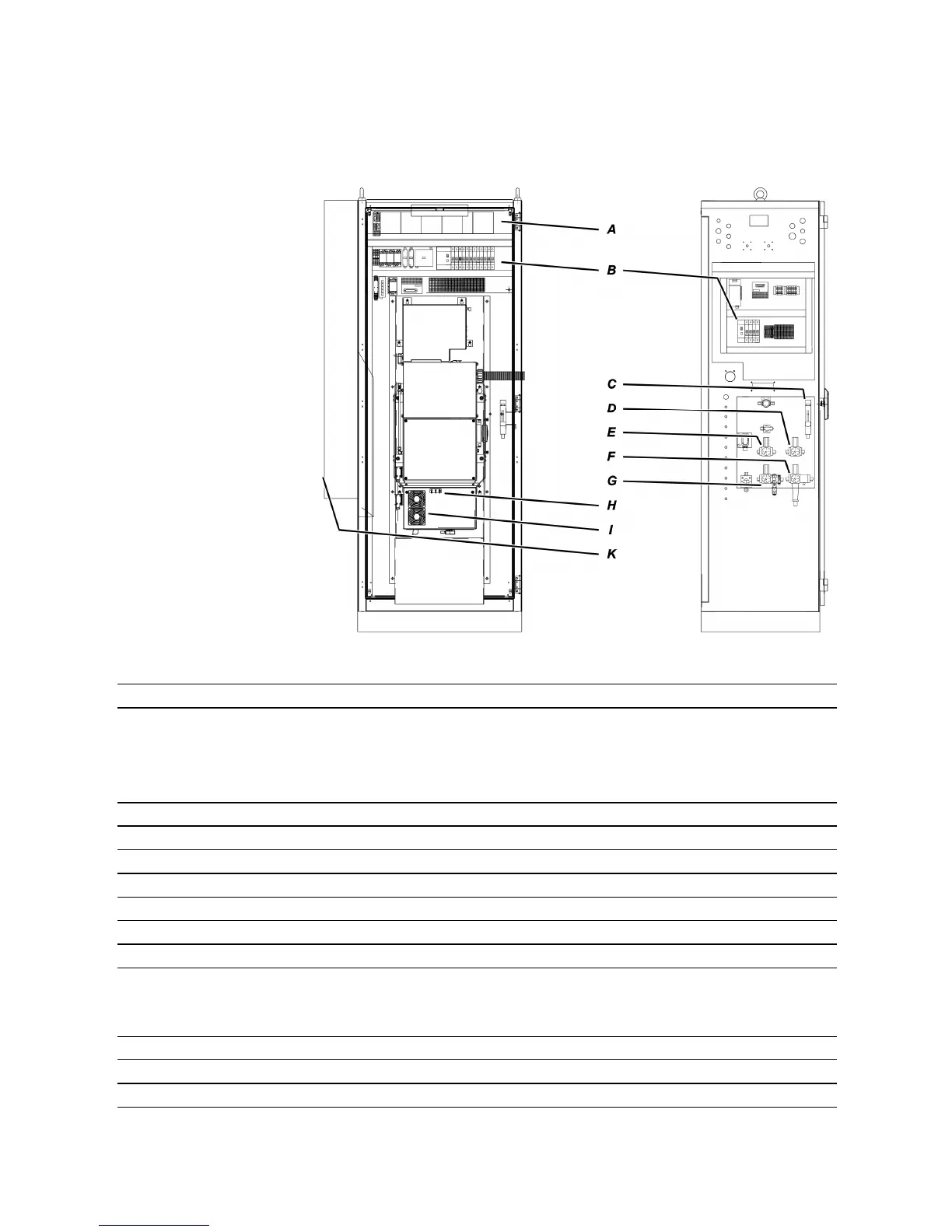
Internal view of the analyzer cabinet
Visual inspection
External instrument air regulator 5.5 to 7 bar
External gas cylinder pressure reducers:
Zero gas, O
2
analyzer (3 vol. % O
2
in N
2
)
Combustion gas, VOC analyzer (H
2
)
Zero gas, VOC analyzer (N
2
or zero gas O
2
analyzer)
Span gas, VOC analyzer (propane in N
2
)
1.5 ± 0.1 bar
1.2 ± 0.1 bar
1.5 ± 0.1 bar
1.5 ± 0.1 bar
A
Status LEDs of the analog and digital output modules Green
1)
B
Circuit breakers and ground fault circuit interrupters activated ON
C
Purge gas flowmeter 125 l/h
D
Instrument air pressure regulator, combustion air, VOC analyzer (–J86) 1.2 ± 0.1 bar
E
Instrument air pressure regulator, purge air, spectrometer (–J88) 2.0 ± 0.1 bar
F
Instrument air regulator with filter (–J85) 5.5 bar
G
Instrument air pressure regulator, injector air (–J96) 4.5 ± 0.1 bar
H
Status LEDs on the cover of the FTIR E-Box "Power" Green
"Status" Green
"Network" Orange/Green flashing
I
Filter mattes on the cover of the FTIR E-Box White
K
Cooling unit display Actual temperature value (target: 25°C)
Filter mattes in cabinet fan and exit filter White
1) When not all channels are connected in an analog output or analog input module the status LED
lights red also in normal operation.