Do you have a question about the ABB Endura AZ20 and is the answer not in the manual?
Details about the AZ20 model for safe area use, including remote and integral versions.
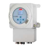
Details about the AZ30 model for hazardous area use, including remote and integral versions.
Defines functional safety of electrical/electronic/programmable electronic safety-related systems for manufacturers and suppliers.
A failure that has the potential to place the safety-related system in a dangerous state or render it inoperative.
A system that performs safety functions to achieve or maintain a safe plant condition.
A specified function performed by a safety-related system to achieve a safe condition during hazardous events.
Securing the device configuration to prevent unauthorized changes that may affect the safety function.
Procedure for resetting a forgotten password, requiring contact with ABB.
Instructions for calibrating AZ20 and AZ30 devices.
On-site inspection procedures, including manual calibration and component checks, for alarms or failed calibration.
The ABB Endura AZ20 and AZ30 Oxygen Analyzers are designed for use in safety-related applications, providing continuous oxygen percentage content measurement in combustion gas analysis. These analyzers generate an analog signal (4 to 20 mA) proportional to the oxygen content, which is then fed to a downstream logic unit, such as a PLC or a limit signal generator, to monitor for exceeding specified maximum or minimum values. The system is engineered to achieve or maintain a safe state in respect of specific hazardous events, making it suitable for critical industrial processes where precise oxygen monitoring is essential for safety.
The AZ20 and AZ30 analyzers are available in both safe area (AZ20) and hazardous area (AZ30) versions, and can be configured as remote or integral units. The core components considered within the safety system boundary include the AZ20 or AZ30 probe, the AZ20 or AZ30 transmitter, and, for remote versions, the interconnecting cable. The safe operation of any components beyond these is outside the scope of the safety documentation. The device is designed for continuous use, with failure rates based on 8760 hours per year, and auto-diagnosed failures are assumed to be addressed within 48 hours, while undiagnosed failures are revealed through a proof-test interval of one year.
The Endura AZ20 and AZ30 analyzers offer a user-friendly interface for configuration and operation. Upon power-up, Operator Page 1 is displayed, showing current process values, which is the normal operating state. Users can access the Operator Menu for additional information and settings. The device supports different access levels: Standard, Advanced, and Service, each with varying permissions for parameter changes.
Configuration of the transmitter involves setting various parameters that can affect the safety function. These include:
The device also features test gas configurations for calibration:
A critical aspect of the device's usage in safety-related systems is the protection against unauthorized access. Once configuration is complete, the device must be protected, as unauthorized changes to parameter settings can affect the safety function. Passwords for Standard and Advanced access levels can be set in the Device Menu > Security setup. These passwords are not set at the factory and must be configured by the end-user. In case of a forgotten password, a reset option is available by contacting ABB.
The analog signal from the transmitter is considered safe after a 2-hour warm-up time or once the heater output stabilizes. A dangerous error, defined as the transmitter output no longer responding to the input signal or deviating by more than 2%, has a maximum reaction time of less than 10 minutes. The device is permitted for use in safety-related systems only within the first 20 years after its production, which forms the basis for the calculated failure rates. The ambient temperature for use in a safety-related system must be above -40 °C, with the upper limit defined by the operating instructions. When measuring corrosive media, users must adhere to the limitations specified in the operating instructions or data sheet. The operator is responsible for selecting the correct version of the probe or transmitter.
Regular maintenance and proof testing are crucial for ensuring the continued functional safety of the Endura AZ20 and AZ30 analyzers. In accordance with IEC61508, the safety function of the measuring device must be checked at appropriate time intervals, which the operator determines and accounts for in the probability of failure calculation. The proof test must verify correct operation of the device, and the MTBF (Mean Time Between Failures) figures assume annual tests at a minimum.
Maintenance procedures include:
The safety integrity levels (SIL) for the Endura AZ20 and AZ30 are certified by Technis, indicating their suitability for use in low and high demand safety functions. As a simplex item (hardware fault tolerance of 0), the analyzer is suitable for SIL 2 in low demand and SIL 1 in high demand applications. This certification is based on an FMEA and data addressing random hardware failures and architectural constraints, with the assessment considering failure modes such as failure to respond to a specific level change of oxygen with an appropriate 4-20mA output, and spurious response despite no valid change. The certificate emphasizes that the product must be used in accordance with the assumptions, limitations, and intervals stipulated in the reliability/integrity report, and that the manufacturer maintains a credible level of Functional Safety Management. Periodic reviews (at least every 2 years) of the design, defect records, and FSM procedures are recommended to ensure ongoing compliance.
| Category | Measuring Instruments |
|---|---|
| Type | Zirconia Oxygen Analyzer |
| Power Supply | 100 to 240 VAC, 50/60 Hz |
| Response Time (T90) | <5 seconds |
| Process Temperature | Up to 1400°C |
| Output | 4-20 mA |
| Probe Length | 0.4m to 4.0m |
| Operating Humidity | 0 to 95% RH, non-condensing |
| Enclosure Rating | IP65 |