ACF5000 FTIR ANALYZER SYSTEM | OI/ACF5000-EN REV. A 39
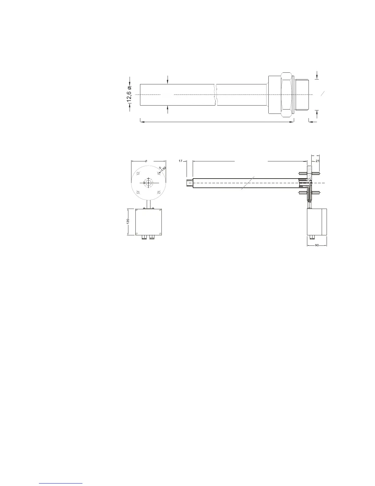
Probe tube type 40
L1 = length of the probe tube (dimensions in mm)
L1 = 500/1000/1500/2000/2500 mm
Probe tube type 42
(dimensions in mm)
If the PFE2 filter unit with standard protective box (450 x 450 x 400mm)
is mounted to the heated, probe tube type 42, the electrical connections
on the probe tube must be connected to the connected to the terminal
box of the filter unit; in this case, the small terminal box, which is part of
the heated probe tube, is not required.
It must be ensured that the sample gas in the gland base, which is in-
stalled between the type 42 heated probe tube and the PFE2 filter unit,
does not fall below operating temperature. The same applies for the wall
tube with assembly flange. Insulation and, where necessary, heat tracing
is required for this purpose.
G
3
4
L1
1